


Hardware Installation
2−31CM 4000 Installation and Operating Manual
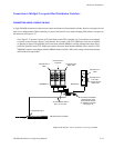
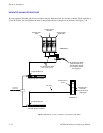
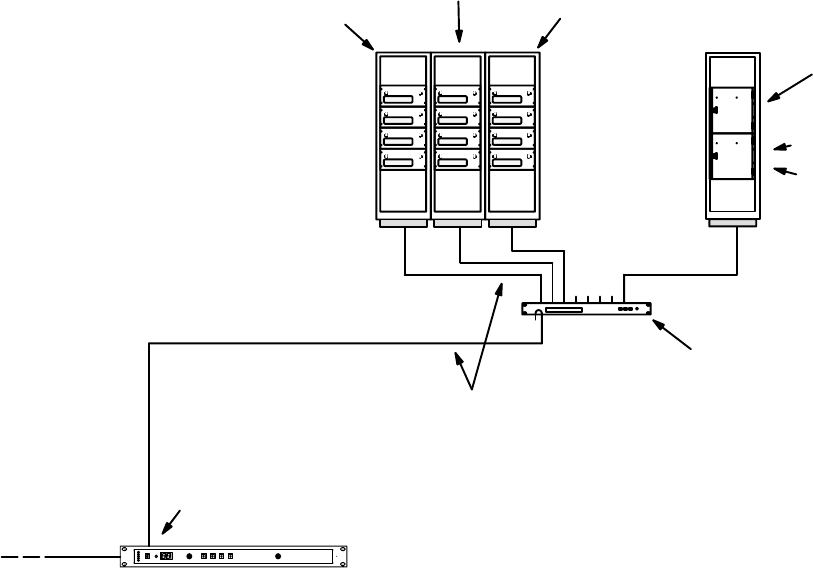
Connection to Multiple Crosspoint Bus Distribution Switchers
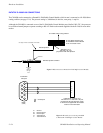
CONNECTION USING A SINGLE CM 4000
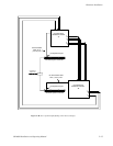
A single CM 4000 control board can be used to control more than one Crosspoint Bus switcher; however, each physical level
must have a unique number. When expanding a system in the field, this may require changing DIP switches or jumpers on
the hardware. See Figure 2−37.
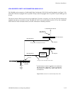
Note: Figure 2−37 pictures a mixture of TVS and Venus routers. This is possible only if all switchers are configured
to operate on the same type (Super) Crosspoint Bus. For example, older TVS 2000 matrix cards are not capable
of operating on Super Crosspoint Bus, but a newer State machine PROM is available which permits Super Cross-
point Bus operations (each TVS 2000 board requires the newer State Machine PROM). Later versions of TVS
2000/3000 switchers were shipped with this PROM already installed; a DIP switch setting selects between Super
and Extended Crosspoint Bus.
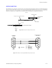
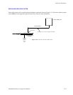
Figure 2−37. Multiple switcher installation with single CM 4000.
CC−2010 Matrix cables.
50 ft. (15.2 m) max.
Physical level 3
Video
Physical level 4
Left audio
Physical level 5
Right audio
Physical level 1
Video
Physical level 2
Left audio
Physical level 6
Right audio
“NEWSROUT” “MAINROUT”
CB−3000 Control Buffer.
Required when more
than 50 matrix boards
are installed in switcher.
See page 2−6.
Crosspoint Bus port
CM 4000 System Controller
LAN