


Control Panel Operation
CP 300 Series
6−3CM 4000 Installation and Operating Manual
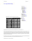
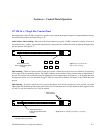
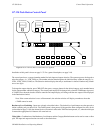
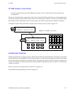
CP 320 Push Button Control Panel
Figure 6−4. CP 320 Push Button Control Panel (as supplied).
CHG
OUT
CHG
VID
CHG
A1
CHG
A2
CHG
A3
CHG
A4
CHG
A5
DESTINATION SELECTION STATUS
CAM1VTR2 VTR1
VTR
1
CG
2
NET
3
VCR
4
CAM
5
AUX
REM
6
FILM
7
PTCH
8
STU
9
TEST
0
EJ SS
MISCFSSAT TAKE
PROT
Installation of this panel is shown on page 2−37. For a general description, see page 2−40.
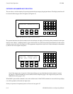
The control panel uses a category/number method for both input and output selection. The operator presses the keypad to
select the category, i.e., VTR, CAM, etc. The number selection then designates the individual entry within the category, i.e.,
VTR1, VTR2, CAM1, CAM2, etc. The Selection window displays the entry as each button is selected. Numbers may contain
one or two digits.
To change the output selection, press CHG OUT, then press a category button for the desired category, and a number button
for the output number within that category. The control panel output will be changed only when the TAKE button is pressed.
A TAKE will not be made, but the switcher controller and output display will change and the new output will be displayed
in the Destination window.
Note: If the current selection is not a valid mnemonic, the selection window will display a number to show that
a TAKE cannot be made.
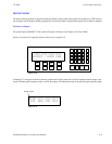
Breakaway Level Switching - Inputs are selected as described above. The desired level push buttons are then pressed to
initiate switching only on those levels. The TAKE button is then pressed. If the panel has been configured for sticky levels
(as described on page 5−108), the selected levels will remain in effect after TAKE has been pressed; i.e., when the next input
is entered the appropriate level buttons will come back on.
Video Splits - Combinations of the Breakaway Level buttons and the Category/Number buttons can be used to create a video
split. The input and output selections are made as described above.