


Configurator
Switcher Input Table
5−48 CM 4000 Installation and Operating Manual
Switcher Input
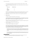
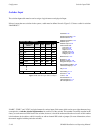
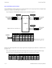
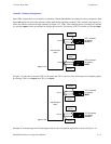
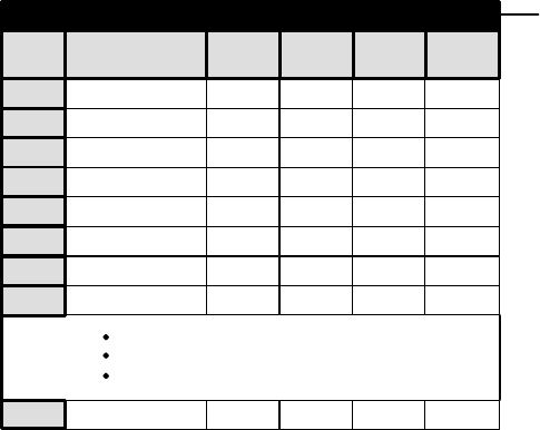
The switcher input table must be used to assign a logical name to each physical input.
If there is more than one switcher in the system, a table must be defined for each. Figure 5−35 shows a table for switcher
“MAINROUT.”
1
Name
BARS
RIGHT
VIDEO
2 TONE
3TC
4 VT01
5 VT02
6
7
8
BLK
VT03
VT04
LEFT TC
000
001
002
003
004
VT05 005
000P
001
002
003
004
005
000P
001
002
003
004
005
000P
001
002
003
004
005
064P
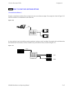
Switcher Input − MAINROUT
064I
000I 000I 000I
000I
000I060I 060I
Figure 5−35. Switcher input table (example).
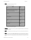
Logical Input
Password 5−22
Network Description 5−27
Serial Protocol 5−30
Switcher Description 5−35
Switcher Input
Switcher Output 5−55
Control Panel Sets
Level set 5−58
Input set 5−62
Output set 5−78
Override set 5−96
Sequence set 5−99
Category set 5−101
MPK Devices 5−107
Machines 5−135
Machine Control 5−139
Delegation Groups 5−149
Status Display Header 5−150
VGA Status Display 5−151
Tally 5−152
Path Finding 5−174
Exclusion 5−188
Y Line 5−189
Time Standard G−11
Video Reference G−14
CM VGA Options H−1
“BARS,” “TONE,” and “VT01” are logical names for various inputs. Each name, which can be up to eight characters long,
corresponds to a switcher physical input number for each level of the switcher. This number is normally attached at the
factory to each connector on the back of the switcher; however, it should be understood that the real source of this number
is the hardware device address, which is usually set with an internal DIP switch or jumper. (For more information, refer to
the manual supplied with the particular switcher.)