


Configurator
Tally
5−173CM 4000 Installation and Operating Manual
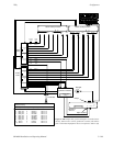
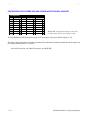
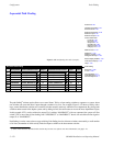
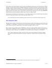
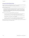
Figure 5−150. Tables for system shown in Figure 5−149.
Tally Device Opto Logical Output Tally
1 XMIT
2 MCS_TLY 0 MCSM1 TALLY1 /4
3 MCS_TLY 1 MCSM2 TALLY1 /4
4 MCS_TLY 2 MCSK1 TALLY1 /4
5 MCS_TLY 3 MCSK2 TALLY1 /4
6 MCS_TLY 6 MCSBP TALLY1 /4
7 TALLY1 0 PROD1 TALLY1 /3
8 TALLY1 1 PROD2 TALLY1 /3
Tally Dependency
Tally Device Relay Logical Input
1 TALLY1 0 VT01
2 TALLY1 1 VC02
3 TALLY1 2 VC01
4 TALLY1 3 PRD
5 TALLY1 4 MCS
Tally Relay
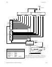
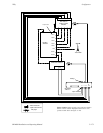
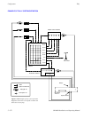
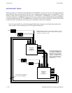
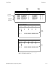
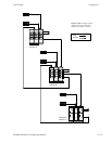
The following discussion refers to Figures 5−149 and 5−150 above. All references to “inputs” and “outputs” are from the
routing switcher point of view. Only video is shown in this example.
The system finds unqualified output “XMIT” on Tally Dependency table. All sources switched to this output
will be tallied. The system checks the routing switcher status tables and finds that input “MCS” (the master
control switcher) is switched to output “XMIT.”
The system locates “MCS” on Tally Relay Descriptions table, according to which relay no. 4 of MI 3040
“TALLY1” should be turned on. This turns on the tally light next to the MCS.
Tally 1, relay 4 is located on the Tally Dependency table. There are five entries, one for each possible source
for the MCS. Each depends (is conditional) on relay 4 to be closed in order to point back to a tally light.
The system checks the MCS (“MCS_TLY”) to determine which source has been selected; in this case it is
output “MCSM1.” The system looks at the routing switcher status table and finds that input “PRD” (the pro-
duction switcher) is switched to output “MCSM1.”
The system locates “PRD” on the Tally Relay Descriptions table, according to which relay 3 of Tally 1 should
be turned on. This relay turns on the tally light next to the production switcher.
Tally 1, relay 3 is located on the Tally Dependency table. There are two entries, one for each possible router
output to the production switcher.
The system now checks opto−isolators 0 and 1 of Tally 1 to determine which source has been selected by the
production switcher. Opto−isolator 0 is energized, meaning that output “PROD1” is selected. (In other words,
relay 3 is ANDed with opto 0.) The system looks at the routing switcher status table and finds that input
“VT01” is switched to output “PROD1.”
The system locates “VT01” on the Tally Relay Descriptions table, according to which relay 0 should be turned
on. This turns on the tally light next to the VTR.