


Hardware Installation
2−40 CM 4000 Installation and Operating Manual
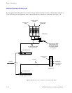
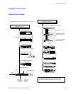
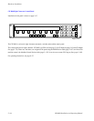
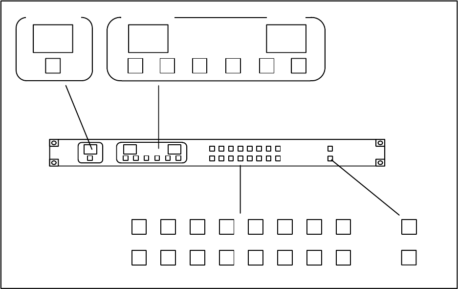
CP 320 Push Button Control Panel
Installation of this panel is shown on page 2−37.
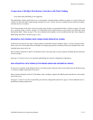
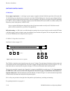
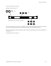
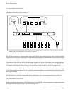
Figure 2−45. CP 320 Push Button Control Panel (as supplied).
CHG
OUT
CHG
VID
CHG
A1
CHG
A2
CHG
A3
CHG
A4
CHG
A5
DESTINATION SELECTION STATUS
CAM1VTR2 VTR1
VTR
1
CG
2
NET
3
VCR
4
CAM
5
AUX
REM
6
FILM
7
PTCH
8
STU
9
TEST
0
EJ SS
MISCFSSAT TAKE
PROT
The CP 320 is a full−matrix, category/number control panel. The left-most mnemonic display shows switcher destination
(output being controlled), the center display shows the input category/number just selected, and the right indicates switcher
status (input now switched to the destination shown).
Sixteen buttons in the center are labeled with input/output categories; this allows the first button press to designate the cate-
gory and the second button press to designate the selection number. The factory−supplied categories (“VTR,” “CG,” etc.) can
be changed by installing new labels (see page 2−58) and creating a custom category set (see Step 5 on page 5−66.)
Two buttons are located on the far right, the top button for protecting an input and the bottom button for performing a TAKE
of the selected input/output. Buttons are also provided for changing the output to be controlled and for selection of specific
levels (split switching).
The CP 320 panel is configured using the MPK Devices table (page 5−107). For operating instructions, see page 6−3.
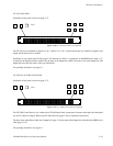
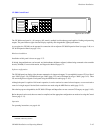
CP 328 Push Button Control Panel
Hardware installation and operation of the CP 328 is the same as the CP 320. Software configuration is slightly different due
to the eight−character display windows. See Step 10 on page 5−69.