


CM 4000 Installation and Operating Manual T−1
Appendix T
Grass Valley 8964 OMD (On Monitor Display) module
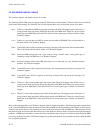
The 4−channel GV 8964 OMD (or on−screen display) board, which is based on the 8964 ENC SDI to NTSC/PAL Encoder
Module, mounts in the 8900 TFN−V Module Frame. In this application, each of the four channels can insert an 8−character
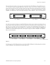
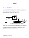
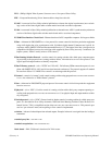
status mnemonic into a digital video stream and display the result on the analog output. Figure T−1 shows the status
mnemonic “CAMERA 1” inserted into one of the OSD board’s four video channels.
Each module frame can contain 10 modules for a total of 40 outputs per frame.
Figure T−1. Example of OSD application. The device names shown correspond to those used in the Jupiter Configuration Procedure
discussion below .
CM 4000 running
AccuSwitch
application
Digital video router
Crosspoint Bus
PS 1PS 2
LOCK
LOCK
FAULT
IP Switch
“MNF1” 8900TFN−V Module Frame
with
“OSD1,” “OSD2,” ”OSD3,” and “OSD4” channels provided by 1 8964OMD OSD
Module
CAMERA 1
Digital
Analog
Jupiter
LAN
Each 8964 channel is associated with a particular Logical Output of the router. The source mnemonic is displayed as white
characters over a black background in the lower part of the screen.
The CM 4000 / AccuSwitch communicates to each Module Frame via the Jupiter LAN and a TCP connection.
The OSD also has the ability to display the current time on a separate line.