


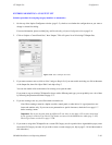
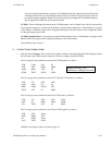

Configurator
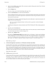
CP Output Set
5−89CM 4000 Installation and Operating Manual
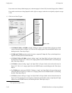
15. Thomson Broadcast Automation / External Computer
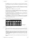
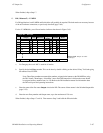
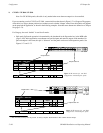
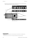
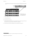
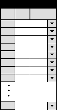
If you are entering a set for a serial control device, you will need a table similar to that shown in Figure 5−70.
Figure 5−70. Serial Output Set table.
1
Output Set − ALAM−OUT
2
2
3
Entry
QC
VT01
Output
3
4
VT02
4
5
5
6
6 VTO5
VT03
VT04
1
7
7
8
8 VTO7
VT06
n
n VTnn
Logical
The purpose of the table is to establish a unique “Entry” number for each switcher “Output” name. In Figure 5−70, Entry
number “1” is associated with Output name “QC.” The Entry number is the number that the serial control device must
send to Jupiter. When the Entry number arrives, the software checks this table to find the associated Output name; then
the Switcher Outputs table (page 5−55) is checked to find the corresponding physical Output number.
Note: For Thomson Broadcast Automation systems, it is suggested that you print out this Output Set; you
will need this information when setting up the Automation Switcher Initialization menu. The Output names
entered on the Jupiter Output Set table must be in the same order as they are on the Automation table. Any
changes made to one table must also be made to the other.
When finished, skip to Step 17.