


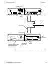
Configurator
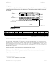
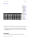
Machine Control Table
5−141CM 4000 Installation and Operating Manual
ASSIGNING (LINKING) MACHINES TO CONTROL PANELS
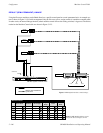
The Jupiter system has an automatic machine assignment function, whereby control of a VTR is linked to a remote panel based
on the VTR being switched to a destination associated with that panel. In other words, machine control follows the routing
switcher.
Note 1: The GUI machine control panel, if installed in the system, bypasses the machine linkage process described
below.
Note 2: As described on page 5−147, it is possible to link machines to control panels even if those machines do not
pass through the routing switcher. However, this will still require an understanding of the “follow−the−switcher”
technique described below.
Note 3: As a further variation, the “follow switcher” scheme can be bypassed entirely, with machines assigned by
default to specific control panels on a semi−permanent basis. See page 5−146.
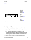
Summary of linkage system setup:
• The switcher inputs, outputs, category names/numbers, etc. must already be established.
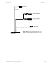
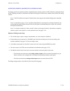
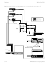
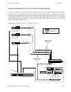
• Each machine must be connected to a CM 4000 System Controller and the protocol for the bus leading to the
machine established. See page 5−142 for an example system.
• All machine control panels are described. In most cases, this is done using the MPK Devices table.
• The device names of all VTRs must be established on the Machine table (page 5−135).
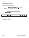
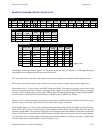
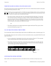
• The Machine Control table is then used to associate machines and control panels to the router:
— The table must show the names of the routing switcher outputs which are wired to the destination (a pro-
duction switcher, in this example) that is associated with a particular machine control panel.
— The table must include the routing switcher input names associated with each VTR.
The linkage setup procedure is described in detail on the following pages.