


L−1CM 4000 Installation and Operating Manual
Appendix L
Special Configuration Requirements: Venus DM 400/400A Data Matrix Switching
Note 1: The following discussion applies only to older model Venus switchers equipped with DM 400 or DM 400A
Data Matrix boards. Newer model Venus systems are equipped with the DM 400B Data Matrix boards; these
boards have software−configurable rear−panel pinout functions and do not require crossover or Y−line cables.
§
The Jupiter system can be used to control RS−232, RS−422, and RS−423 data switchers.
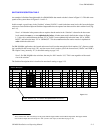
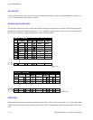
DM 400/400A data switchers employ a “reverse” switching technique, where one level is used to switch data from a control-
ling device (such as an editor) to a controlled device (such as a VTR); a second level is used to return data to the controller.
The return path is switched automatically by the control system.
The following discussion applies specifically to a Venus DM 400/400A data matrix switchers in an RS−422 machine control
application; however, the same concepts generally apply to other Grass Valley Crosspoint Bus data switchers and protocols.
An important difference is that the Venus DM 400/400A data matrix switcher uses the same physical level number for both
the forward and reverse levels; whereas the TVS/TAS series data matrix switchers use different physical level numbers.
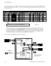
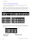
HARDWARE CONNECTIONS
For complete information regarding jumper settings and cabling, refer to the technical manual supplied with the switcher.
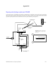
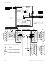
An example of an RS−422 Venus system is shown on page L−2.
Note 2: As shown on page L−2, the cable used to connect the control device (e.g., editor) to the DM 400/400A
switcher is a cross−over type cable.
Note 3: If you wish to use or build a cable for the editor that has the standard “straight−through” pin−outs, you may
elect to use this straight−through cable with a short crossover cable or connector. The short crossover cable/con-
nector could be attached permanently to the Venus rear panel.
§
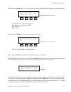
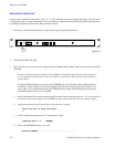
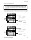
Type and model of switcher card is shown on front edge of printed circuit board.