


Control Panel Operation
CP 3832 / 3864
6−110 CM 4000 Installation and Operating Manual
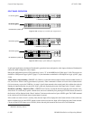
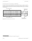
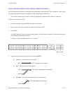
Source Expansion Operation (with “balanced Split” 16 x 16 Main Panel)
For expansion with balanced split
§
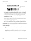
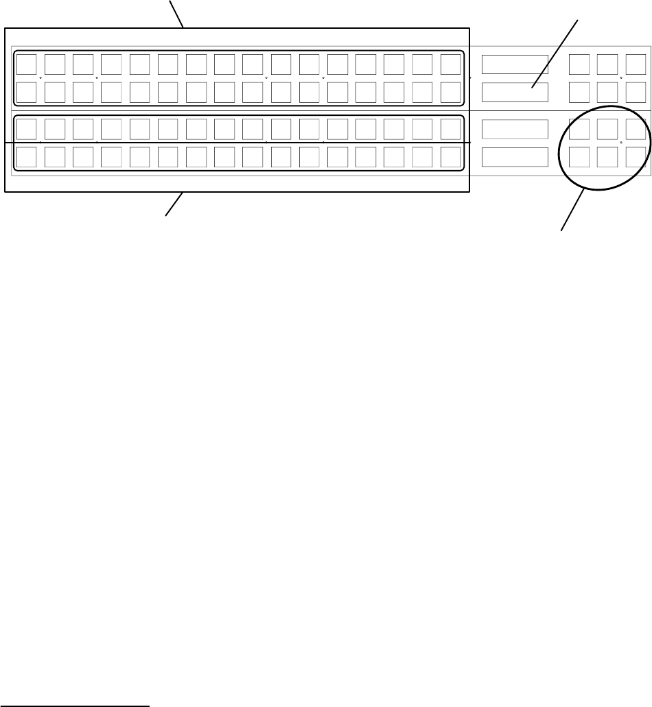
main panel applications, such as illustrated in Figure 6−141, operation is very similar to
that described on page 6−106. The main difference is that only the Main panel’s control buttons (“LEVEL,” “TAKE,” etc.)
are normally used. On the expansion panel(s), the control buttons are not illuminated and the word “Source” always appears
in the Preset window.
VTR1 VTR2 VTR3 VTR4
VTR5 VTR6 VTR7 VTR8
CAM1 CAM2 CAM3 CAM4
CAM5 CAM6 CAM7 CAM8
BLACK
BARS TONE CG−1
SILE
NCE
CG−2 CG−3 CG−4
EBS1 EBS2 TEST1 TEST2 FDL1 FDL2 FDL3 FDL4
Level Menu Clear
Prot/
Lock
Pre−
set
Take
CURRENT
PRESET
VTR−001
SOURCE
Figure 6−141. CP 3832s configured as 48 x 16 control station.
Level
Menu Clear
Prot/
Lock
Pre−
set
Take
CURRENT
PRESET
VTR−001
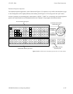
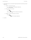
Illuminated control buttons
indicate Main panel
All source buttons glow green
“SOURCE” indicates
expansion panel
STU1 STU2 STU3 STU4
EDIT1 EDIT2 EDIT3 EDIT4
PST PGM AIR KEY1
KEY2
BACK
UP
BY
PASS
XMIT
VTR1 VTR2 VTR3 VTR4
VTR5 VTR6 VTR7 VTR8
AUX1 AUX2 AUX3 AUX4
MON1
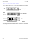
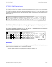
All destination buttons glow amber
MON2 MON3 MON4
§
For a discussion of balanced and unbalanced split configurations, see page 2−49.