COPYRIGHT
©
1999 CANON INC. CANON imageRUNNER 600 REV.1 JAN. 2000 PRINTED IN U.S.A.
4-31
CHAPTER 4 IMAGE PROCESSING SYSTEM
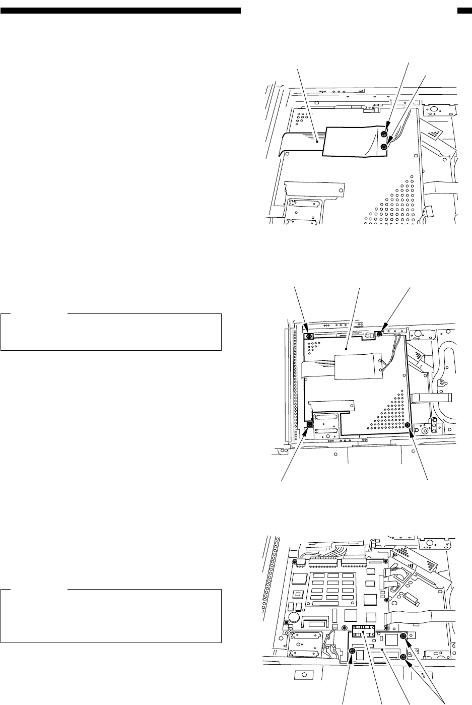
6) Remove the two screws [9], and detach
the flat cable [10].
7) Remove the four screws [11], and detach
the image processor cover [12].
Caution:
Take care not to damage the flat cable re-
moved in step 6).
8) Remove the three screws [13], and detach
the original orientation detection PCB
[14].
Caution:
Take care not to damage the connector
[15] of the image processor PCB and the
original orientation detection PCB [14].
Figure 4-D410
Figure 4-D411
[10]
[9]
[9]
[11]
[11]
[12]
[11]
[11]
Figure 4-D412
[13]
[13] [15]
[14]


