9-64
COPYRIGHT
©
1999 CANON INC. CANON imageRUNNER 600 REV.1 JAN. 2000 PRINTED IN U.S.A.
CHAPTER 9 EXTERNALS/AUXILIARY MECHANISMS
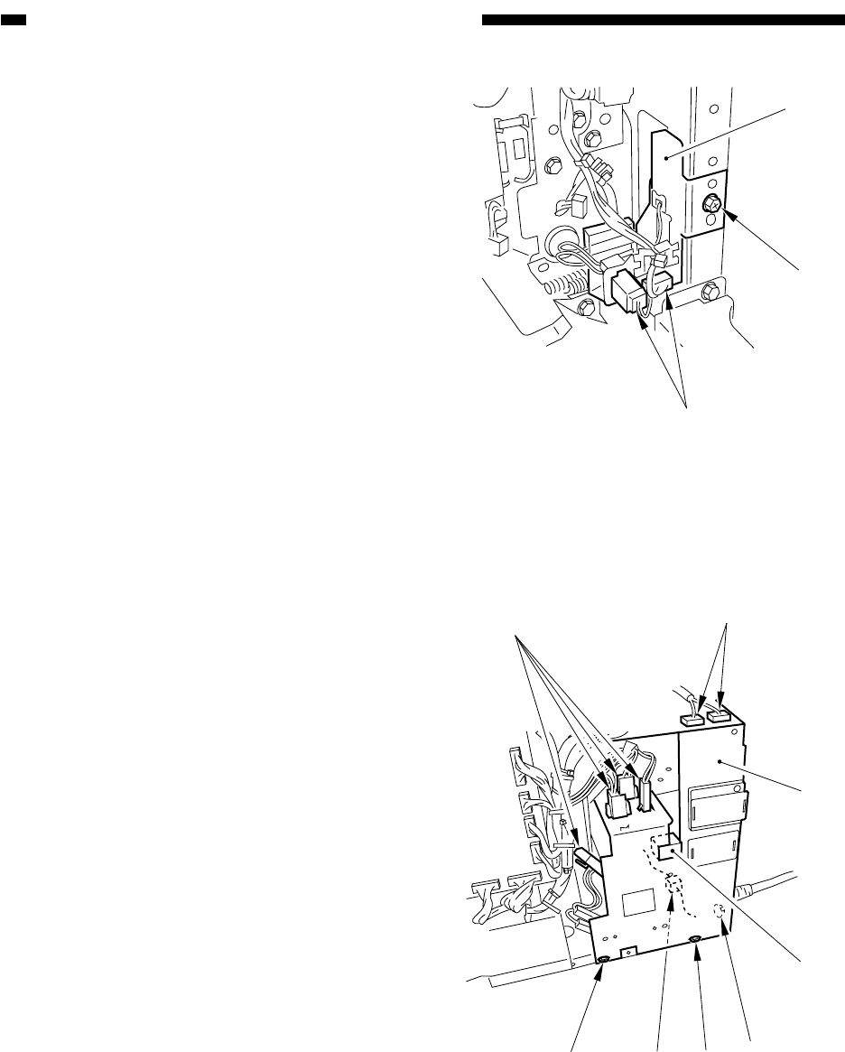
Figure 9-E705
Figure 9-E706
[9]
[7]
[8]
[2]
[2]
[2]
[1]
[1]
[1]
[3]
[4]
4) Remove the screw [7], and disconnect the
two connectors [8]; then, remove the
manual feed tray switching assembly [9].
3. Removing the Drum Heater
Switch Assembly
1) Remove the lower left cover.
2) Remove the three screws [1], and discon-
nect the seven connectors [2]; then, re-
move the power supply cord mount [3],
and release the fixing claw to detach the
drum heater switch [4].


