COPYRIGHT
©
1999 CANON INC. CANON imageRUNNER 600 REV.1 JAN. 2000 PRINTED IN U.S.A.
8-41
CHAPTER 8 FIXING SYSTEM
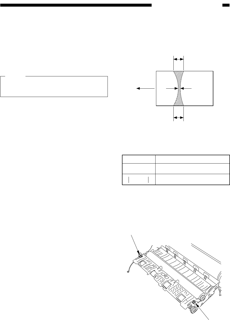
Figure 8-D512
Table 8-D501
Figure 8-D513
Feeding
direction
a
c
b
A3
Center
of paper
Dimensions
7.3mm ± 0.5mm
0.5 mm or less
Measurements*
b
a-c
* Be sure both upper and lower rollers are fully
heated.
[1]
[1]
2) Select COPIER>FUNCTION>FIXING>
NIP-CHK in service mode to discharge
paper.
b. Standards
1) Measure the area shown in Figure 8-
D512.
Note:
a and c are points 10 mm from both ends
of paper.
2) Check to see if the measurements are as
indicated in Table 8-D501; otherwise,
perform c. "Making Adjustments."
c. Making Adjustments
1) Remove the fixing assembly from the
copier.
2) Detach the fixing cleaning belt; then,
clean and remove the oil pan.
3) Remove the two fixing heaters.
4) Open the upper fixing unit.
5) Adjust the nip by two adjusting screws [1]
(front and rear).


