CHAPTER 6 IMAGE FORMATION SYSTEM
6-6
COPYRIGHT
©
1999 CANON INC. CANON imageRUNNER 600 REV.1 JAN. 2000 PRINTED IN U.S.A.
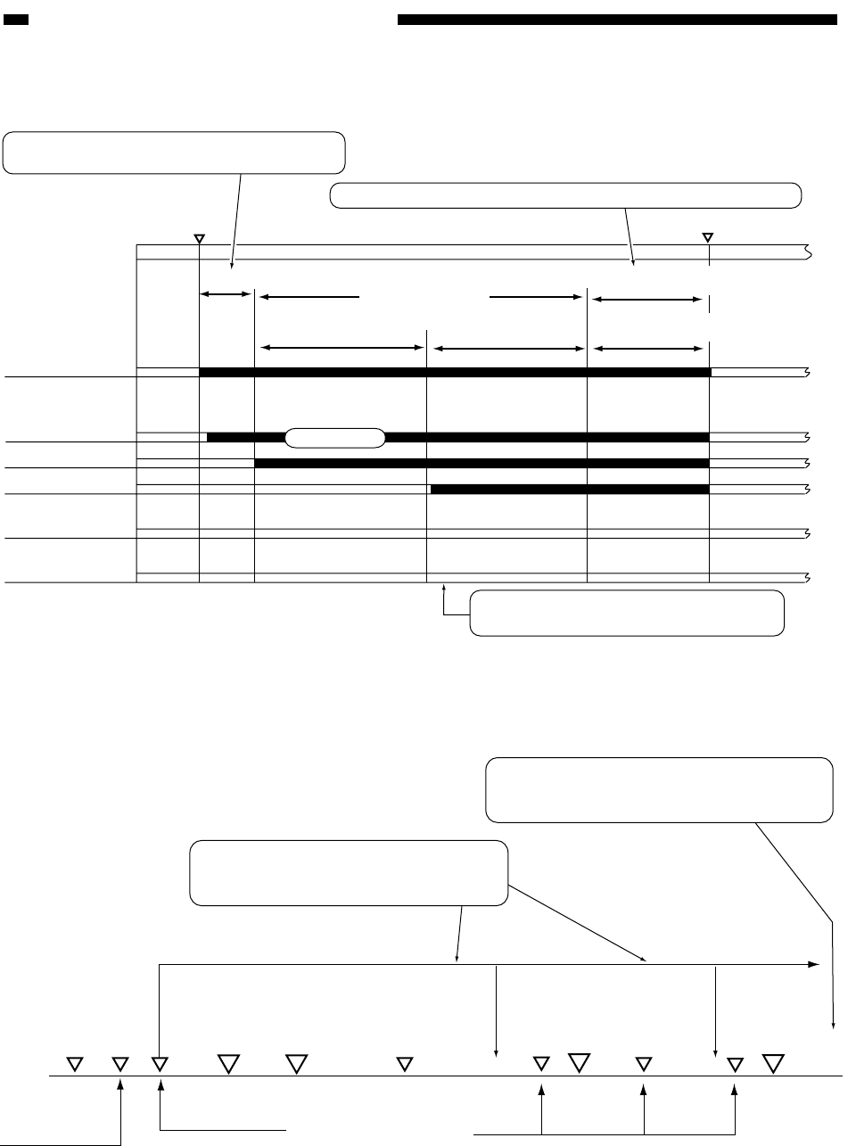
Figure 6-202 Basic Sequence of Operations (potential control)
Figure 6-203 Timing of Potential Control Operations
Figure 6-202 shows the basic sequence (timing) of operations related to potential control.
WMUPR
WMUP
STBY
195˚C
200˚C
Drum motor(M0)
Primary
charging bias
(DC)
Developing bias
AC bias (AC)
Developing bias
(DC)
Grid bias
Laser
Potential stabilization sequence
Fixed value
Optimum grid bias
determined
Optimum laser output
determined
Potential control
Potential control is as when the main power switch is turned on.
A series of charging operations is executed to
stabilize the potential of the drum.
To prevent stray toner, the developing bias
is turned off for non-image areas.
Optimum laser output
determined
Transparency mode
potential control
[1] The control panel power switch is turned on.
[2] The front door is opened/closed.
10 min
60 min
The charging characteristics are likely to have
stabilized at this point, and potential control will
not be executed after this point.
Potential control is executed 10 min and 60
min after the temperature of the fixing
assembly has reached 195˚C.
Main power
switch ON
Potential
control for
transparency
Copy Start
key ON
Potential
control
Potential
control
Potential
control
Fixing assembly temperature at 195˚C
(end of fixing assembly warm-up)
Copy Start
key ON


