


COPYRIGHT
©
1999 CANON INC. CANON imageRUNNER 600 REV.1 JAN. 2000 PRINTED IN U.S.A.
7-7
CHAPTER 7 PICK-UP/FEEDING SYSTEM
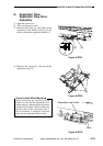
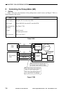
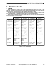
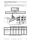
D. Movement of the Lifter
1. Outline
When the deck or the cassette is slid in, the cassette open/closed sensor turns on and, at the
same time, the pickup roller starts to move down, causing the light-blocking plate to leave the lifter
sensor, driving the cassette lifter motor and, ultimately, moving up the lifter.
The lifter keeps moving up until the lifter sensor detects the surface of paper. (In the case of the
deck right/left, a limiter is mounted to stop the lifter if it fails to stop moving up.)
When the deck or cassette open button is pushed, the drive gear of the lifter becomes free to let
the lifter move down on its own weight.
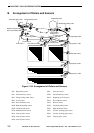
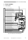
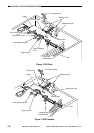
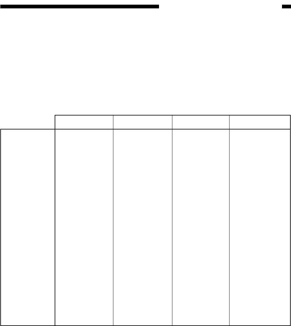
Figure 7-202 Components
Right deck
Deck right open/
closed sensor
(PS23)
Lifter sensor
(PS21)
Deck right paper
sensor (PS22)
Deck right paper
level middle
sensor (PS51)
Deck right paper
level upper sensor
(PS52)
Deck right limit
sensor
(PS24)
Deck right lifter
motor (M13)
Cassette open/
closed detection
Lifter position
detection
Paper presence/
absence detection
Copy paper level
detection
Lifter upper
limiter
Drive motor
Left deck
Deck left open/
closed sensor
(PS33)
Lifter sensor
(PS31)
Deck left paper
sensor (PS32)
Deck lifter paper
level middle
sensor (PS54)
Cassette 2 paper
level upper sensor
(PS55)
Deck left limit
sensor
(PS34)
Deck lifter motor
(M14)
Cassette 3
Cassette 3 open/
closed sensor
(PS40)
Lifter sensor
(PS38)
Cassette 3 paper
sensor (PS39)
Cassette 3 paper
level detection
PCB
(variable resistor)
---
Cassette 3 lifter
motor (M16)
Cassette 4
Cassette 4 open/
closed sensor
(PS45)
Lifter sensor
(PS43)
Cassette 4 paper
sensor (PS44)
Cassette 4 paper
level detection
PCB
(variable resistor)
---
Cassette 4 lifter
motor (M17)