COPYRIGHT
©
2000 CANON INC. CANONimageRUNNER 600 REV.1 JAN. 2000 PRINTED IN U.S.A.
9-31
CHAPTER 9 EXTERNALS/AUXILIARY MECHANISMS
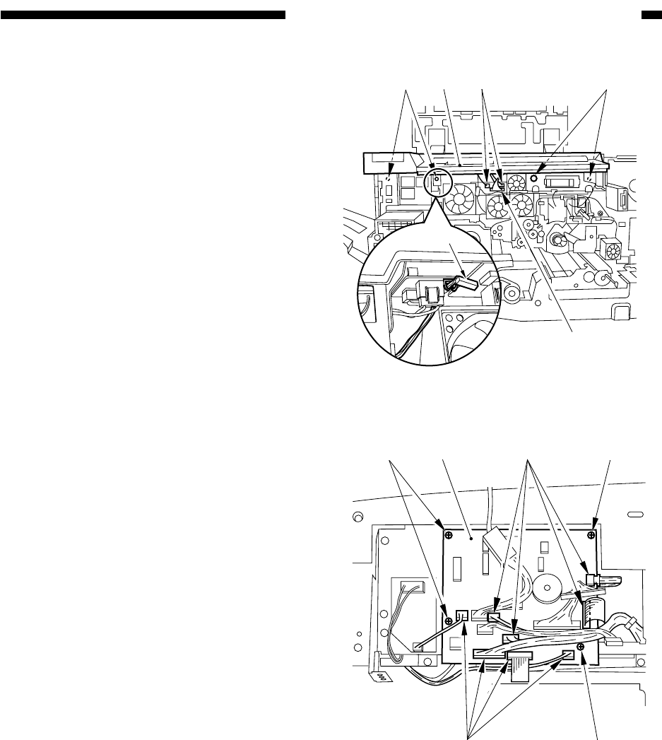
Figure 9-B704
[8]
[9]
[9]
[11] [8]
[10]
[1] [1]
[1]
[2]
[2]
[3]
Figure 9-B705
6) Remove the four screws [8] from the front
cover side, and disconnect the three cables
[9]; then, free the cable [10] from the
cable clamp, and detach the control panel
[11].
2. Removing the Control Panel
Controller (CPU) PCB and the
Control Panel Inverter PCB
1) Remove the four mounting screws [1],
and disconnect the eight connectors [2];
then, detach the control panel controller
(CPU) PCB [3].


