


10-16
COPYRIGHT
©
1999 CANON INC. CANON imageRUNNER 600 REV.1 JAN. 2000 PRINTED IN U.S.A.
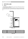
CHAPTER 10 SIDE PAPER DECK
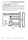
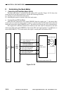
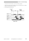
2. Controlling the Deck Lifter Motor (M102)
The deck lifter motor control circuit is located on the side deck driver PCB. (See Figure 10-111
for a block diagram.)
The combination circuit in the diagram consists of various logic circuits, and serves to rotate
the deck lifter motor clockwise or counterclockwise based on the combinations of the deck lifter
motor drive signal (DLMON*) and the deck lifter up signal (DLUP*) from the copier's DC control-
ler and the output signals from various sensors.
The copier's control panel will indicate 'E041' if the deck lifter position sensor (PS104) does
not detect the lifter in about 60 sec after the generation of the deck lifter up signal.
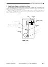
[1] Conditions Making the Lifter Move Up
• The deck is connected to the copier. ! deck set signal (DSET) = '1'
• The deck (compartment) is closed. ! deck open detection signal (DOPND*) = '1'
• The deck (compartment) is closed. ! deck open detecting switch = 'ON'
• deck lifter upper limit detection signal (DLUL) = '0' and deck lifter position detection signal
(DLPD) = '0'
• deck lifter motor drive signal (DLMON*) = '0'
• deck lifter up signal (DLUP*) = '0'
As a result, the lifter moves up.
[2] Conditions Making the Lifter Move Down
• The deck (compartment) is open. ! deck open detection signal (DOPND*) = '0'
• deck lifter lower limit detecting signal (DLLD) = '0' and deck lifter position detection signal
(DLPD) = '0'
• deck lifter motor drive signal (DLMON*) = '0'
• deck lifter up signal (DLUP*) = '1'
As a result, the lifter moves down.