CHAPTER 13 TROUBLESHOOTING
13-16
COPYRIGHT
©
1999 CANON INC. CANON imageRUNNER 600 REV.1 JAN. 2000 PRINTED IN U.S.A.
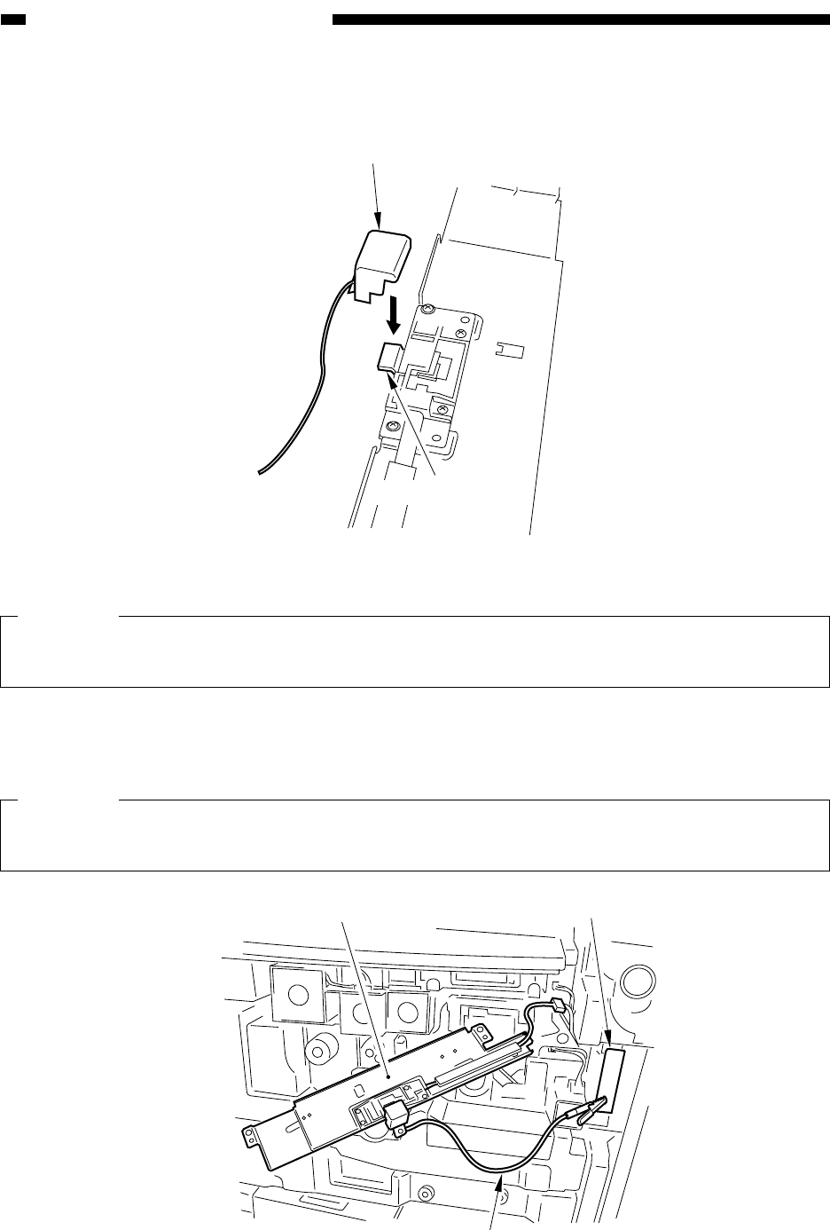
Potential sensor
Potential sensor
tester electrode
Figure 13-C202
Potential sensor support plate
Cable
Support plate (GND)
4) Fit the potential sensor tester electrode (FY9-3041) to the potential sensor.
Figure 13-C201
Caution:
When fitting the tester electrode to the potential sensor, take care so that the magnet of the
electrode will not come into contact with the potential sensor cover.
5) Connect the cable of the potential sensor tester electrode to the support metal plate (GND) of
the potential measurement PCB.
Caution:
Be sure not to bring the clip into contact with the sensor cover by keeping it sufficiently away
from the window of the sensor.


