CHAPTER 3 ORIGINAL EXPOSURE SYSTEM
3-2
COPYRIGHT
©
1999 CANON INC. CANON imageRUNNER 600 REV.1 JAN. 2000 PRINTED IN U.S.A.
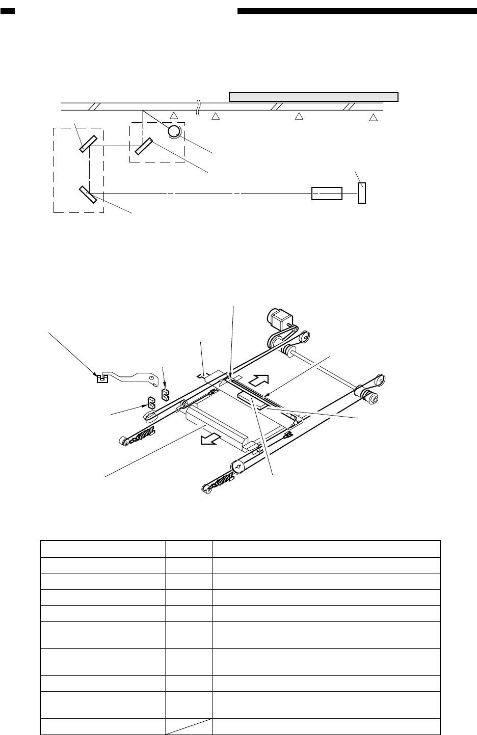
Figure 3-101 shows the major components of the original exposure system.
Figure 3-101 (cross sectional view)
Figure 3-102 (external view)
Table 3-102 Major Components
Copyboard glass
Original
Scanning
lamp
Lens
CCD
No. 1 mirror
No. 1 mirror mount
No. 2 mirror
No. 2 mirror mount
No. 3 mirror
Home position
Small-size
stream reading
point
Large-size
stream reading
point
Image leading
edge
No. 2 mirror mount
Scanner home
position sensor
(PS1)
Image leading
edge sensor (PS3)
Scanner motor (M5)
(forward)
(reverse)
Light-blocking
plate
No. 1 mirror mount
Fluorescent lamp heater (H5)
Scanning lamp (FL1)
Light intensity sensor (PD2001)
Copyboard glass sensor
Component
Description
Fluorescent amp (rated at 43 W)Scanning lamp
Scanner motor
Scanner home position sensor
Image leading edge sensor
Copyboard glass sensor
Light intensity sensor
Fluorescent lamp temperature
sensor
5-phase stepping motor
Photointerrupter (detects the scanner home position)
Photointerrupter (detects the image leading edge)
Photodiode (detects the lamp light intensity)
No. 1 through No. 3 mirrors
Photointerrupter (detects the presence/absence of the
copyboard glass)
Thermistor (detects the fluorescent lamp heater
temperature)
Nickel chrome line (rated at 36 W; stabilizes the
temperature inside the fluorescent lamp)
FL1
M5
PS1
PS3
PS57
H5
PD2001
H5
Fluorescent lamp heater
Mirror
Notation


