COPYRIGHT
©
1999 CANON INC. CANON imageRUNNER 600 REV.1 JAN. 2000 PRINTED IN U.S.A.
2-7
CHAPTER 2 BASIC OPERATIONS
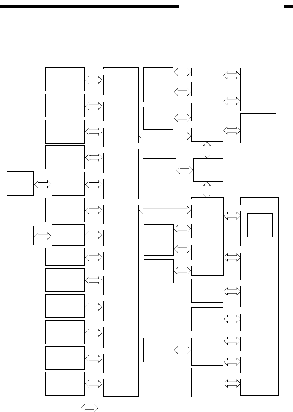
E. Inputs to and Outputs from the Major PCBs
1. Wiring Diagram of Major PCBs
Figure 2-105 Wiring Diagram of Major PCBs
MFC PCB
DC controller PCB
System
mother
PCB
Download
PCB
Image
server
Page
memory
PCB
BD
PCB
CCD
PCB
Laser
driver
PCB 1
Laser
driver
PCB 2
Original
orientation
detection
PCB
Potential
control PCB
Environment
sensor PCB
Cassette 3
paper level
detection PCB
Cassette 4
paper level
detection PCB
Control
Card-V
(accessory)
Copy Data
Controller
(accessory)
Non-stacking
feeding
driver PCB
Scanner
motor driver
PCB
Fluorescent
lamp
inverter PCB
Light
intensity
control PCB
HV-DC
PCB
HV-AC
PCB
Image processor PCB
J3
J802
J3602
J1110
J1102
J502
J520
J521
J506
Laser scanner
motor driver
PCB
J762
J723
J302
J295
J296
J711
J741
J852
J165
J1002
J853
J503
J506
J506
J510
J516
J516
J516
Heater
driver
PCB
J2605
J505
J519
J1407J525
J503
J1405
J1406
J1409
J1461
J1453
J1401
J1003
J1455
J1454
J1108
J1105
J1106
J1107
J1112
J1402
J1015
J1014
J1018
J1019
J1008
J1103
J1403
J3701
J1502
J1353
J1354
J1
J354
J355
Control
panel
power
switch PCB
Key
LED
PCB
Liquid
crystal
display
(LCD)
Control
volume
PCB
Printer
PCB
(accessory)
Control panel CPU PCB
Light
intensity
PCB
J1013
J1010
J1009
J1012
J1004
J1002
Note: The in the diagram indicates connection, NOT the flow of signals.


