3-28
COPYRIGHT
©
1999 CANON INC. CANON imageRUNNER 600 REV.1 JAN. 2000 PRINTED IN U.S.A
CHAPTER 3 ORIGINAL EXPOSURE SYSTEM
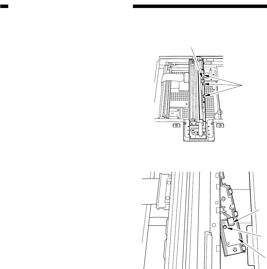
Figure 3-C501
Figure 3-C502
Claw
[1]
[2]
[3]
[4]
C. PCBs
1. Removing the Light Intensity
Control PCB
1) Remove the right glass retainer.
2) Remove the copyboard glass.
3) Remove the screw [1] from the No. 1 mir-
ror mount; then, while pushing down the
three claws, free the intensity control PCB
holder.
4) Disconnect the connector [2] (J165), and
remove the screw [3]; then, detach the
light intensity control PCB [4].


