COPYRIGHT
©
1999 CANON INC. CANON imageRUNNER 600 REV.1 JAN. 2000 PRINTED IN U.S.A.
4-25
CHAPTER 4 IMAGE PROCESSING SYSTEM
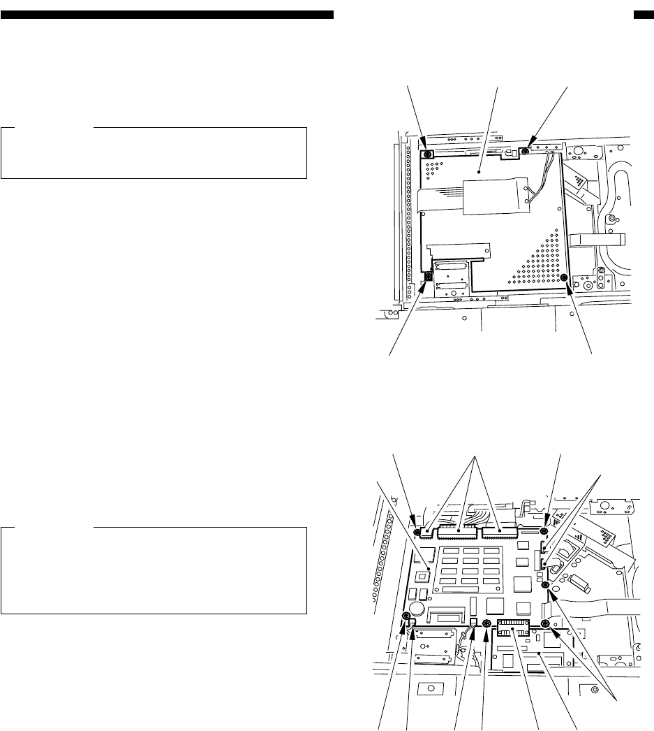
Figure 4-B403
[6]
[6]
[7]
[6]
[6]
[10]
[10]
[10]
[10]
[10]
[9]
[9] [12]
[11]
[8]
[9]
[9]
Figure 4-B404
5) Remove the four screws [6], and detach
the image processor cover [7].
Caution:
At this time, take care not to damage the
flat cable removed in step 4).
6) Disconnect the seven connectors [9] of the
image processor PCB [8], and remove the
six screws [10]; then, detach the image
processor PCB [8].
Caution:
At this time, take care not to damage the
connector [12] of the image processor
PCB and the original orientation PCB
[11].
2. After Replacing the Image
Processor PCB
See G. "Electrical Parts" under II. of
Chapter 13.


