


CHAPTER 3 ORIGINAL EXPOSURE SYSTEM
3-8
COPYRIGHT
©
1999 CANON INC. CANON imageRUNNER 600 REV.1 JAN. 2000 PRINTED IN U.S.A.
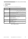
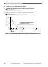
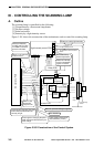
III . CONTROLLING THE SCANNING LAMP
A. Outline
The scanning lamp is controlled for the following:
[1] Temperature by a fluorescent lamp heater
[2] Pre-heat voltage
[3] Initial activation
[4] Intensity by a light intensity sensor
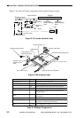
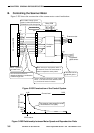
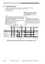
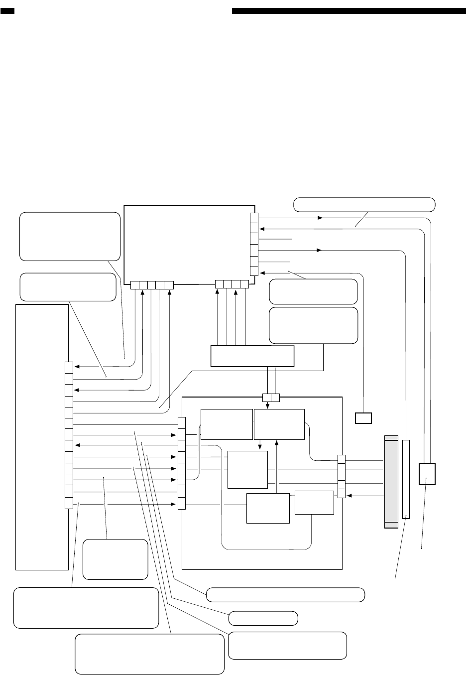
Figure 3-301 shows the construction of the mechanisms used to control the scanning lamp.
Figure 3-301 Construction of the Control System
DC controller PCB
Inverter PCB
J506B
J852
J851J853
J1002
J803
J1001
1
2
3
4
5
1
2
1
2
3
4
5
6
7
8
9
10
11
12
13
0 V
0 V
0 V
38 VU
GND
38 VU
24 VU
24 V
38 V
GND
GND
GND
Scanning
lamp
Light intensity
sensor
To light intensity sensor
Fluorescent heater
Temperature
sensor
FL-PWM
FL-ERR
FL-CLK
FL-TH
FL-GAIN
FL-REF
HEAT-ON
GND
FL-TH
FL-DTCT
FLON
PRH-PWM
PRH-ON
Current
detection
T1001
Activation
voltage
Pre-heat voltage
10
11
12
13
6
7
8
9
Output
control
Light intensity control PCB
1
2
3
4
5
6
1
2
3
4
5
1
3
4
2
Relay PCB
H5
To temperature sensor/scanner
heater
Fluorescent
lamp
transformer
Pre-heat
output
control
Transformer
drive control
When '0' ,the scanner
heater turns on.
When '0', the
fluorescent
lamp turns on.
Pulse signals. Changing the pulse
width increases/decreases the
intensity of light.
Pulse signals used to drive
the transformer (T1001).
Error detection
Voltage to suit the light intensity.
Reference intensity
level for comparison
against FL-DTCT.
Fluorescent lamp
heater temperature
Difference between
FL-REF and FL-DTCT.
FL-PWM is corrected
based on this data.
Pulse signals. Changing the pulse
width increases/decreases the pre-
heat voltage.
When '0', pre-heat voltage is applied.