


COPYRIGHT
©
1999 CANON INC. CANON imageRUNNER 600 REV.1 JAN. 2000 PRINTED IN U.S.A.
11-37
CHAPTER 11 INSTALLATION
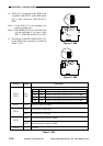
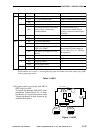
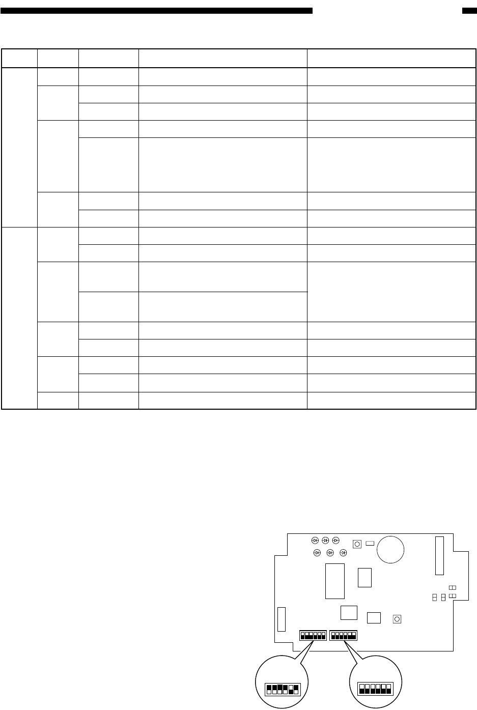
Figure 11-A602
bit
Position
Description
Remarks
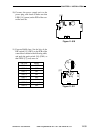
SW1
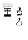
SW5
*1: Set SW5-4 (DIP switch) to OFF if the Control Card-V is used or remote control only by the Copy
Data Controller-A1 is used (i.e., not using ID input, paper size control, toner color control, copy mode
control, paper type control).
1~3
4
5
6
1
2
3
4
5,6
OFF
OFF
ON
ON
OFF
ON
OFF
ON
OFF
ON
OFF
ON
OFF
ON
OFF
For normal operation.
For serial communication.
For IPC communication.
For use of a central control device.
For normal operation or for remote
control using a commercially
available modem.
For RAM clear.
For normal operation.
For factory adjustment.
For normal operation.
For control of Inch papers (11×17,
LTR, LGL, STMT).
For control of AB papers (A3, A4,
B4, B5).
For service mode.
For normal operation.
For group control.
For no group control.
NP6030, NP6060, NP8530, NP9800
Other than above.
Requires the Interface Board-B1.
For remote control using a
commercially available modem,
requires a modem and the Interface
Board-B1.
For controlling paper other than
those on the left, make settings in
service mode. See C.10. "Checking
the Operation."
*1
OFF
Not used.
Table 11-A601
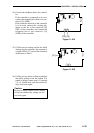
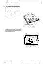
2.3)If group control is not used, shift SW5-4
(DIP switch) to OFF.
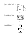
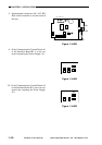
To install the Interface Board-B1, Com-
munication Control Board-A1, or Inter-
face Board-A1, see the descriptions under
"Setting the Board" in their respective In-
stallation Procedures.
16
SW4
SW1
ON
SW5
ON
LED6LED5LED4
LED3LED2LED1
SW2
SW3
JB2
JB1
JA1
JA2
EPROM
SRAM
CPU
IPC
JC9
JC6
JC5
JC8
J5
16
SW1
16
16
SW5
Photocoupler