


CHAPTER 2 BASIC OPERATIONS
2-2
COPYRIGHT
©
1999 CANON INC. CANON imageRUNNER 600 REV.1 JAN. 2000 PRINTED IN U.S.A.
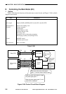
B. Electrical Circuitry
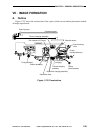
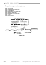
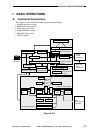
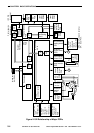
1. Outline
The copier's major electrical mechanisms are controlled by the CPU on the MFC PCB, image
processor PCB, and DC controller PCB. The following tables show the control functions assigned
to each CPU and the ICs and their functions used around the CPUs (RAMs, DIMMs).
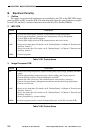
2. MFC PCB
Table 2-101 Control Items
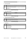
3. Image Processor PCB
Table 2-102 Control Items
Name
CPU
RAM
DIMM
Description
• Controls the fixing temperature, original scanning lamp, high voltage, potential, and toner
supply.
• Controls paper feeding, image processing, scanner reading, and copying sequence.
• Controls printing sequence, output management, and ADF.
• Controls the sorter (accessory) and communications control device (accessory).
• Controls the page memory management mechanism and hard disk image input/output.
• Controls service mode.
• Stores service mode data. (For details, see E. "Backup Battery" in Chapter 9 "Externals and
Auxiliary Control.")
• Stores user mode data. (For details, see E. "Backup Battery" in Chapter 9 "Externals and
Auxiliary Control.")
• Stores pickup/delivery counter readings.
• Controls programs (used to control the input/output ports on the DC controller PCB).
Name
CPU
RAM
DIMM
Description
• Controls the control panel, hard disk, and personal box image management.
• Controls job management, operation status management, and log management.
• Controls PDL image transfer sequence.
• Controls PDL-image processor PCB communications and service mode.
• Stores service mode data. (For details, see E. "Backup Battery" in Chapter 9 "Externals and
Auxiliary Control.")
• Stores user mode data. (For details, see E. "Backup Battery" in Chapter 9 "Externals and
Auxiliary Control.")
• Controls programs.