COPYRIGHT
©
2000 CANON INC. CANON imageRUNNER 600 REV.1 JAN. 2000 PRINTED IN U.S.A
3-21
CHAPTER 3 ORIGINAL EXPOSURE SYSTEM
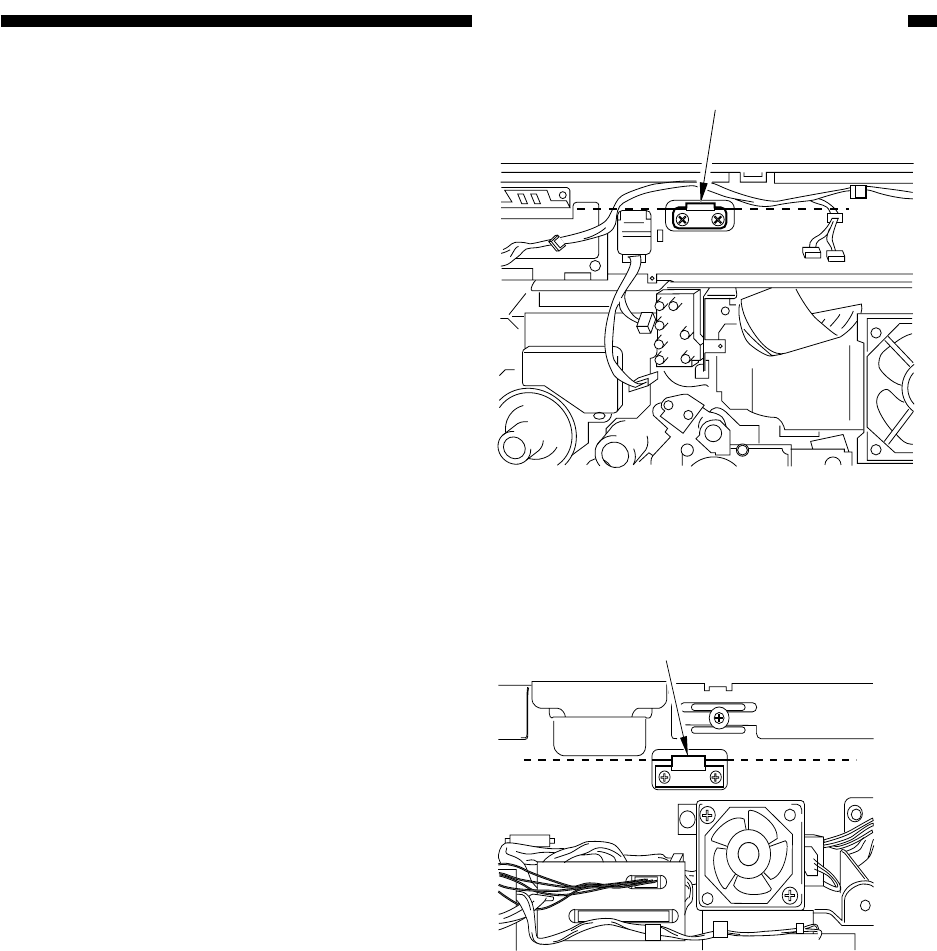
Figure 3-B503
Figure 3-B504
[1]
Front
[1]
Rear
2. Scanner Drive Cable
a. Adjusting the Tension of the Scanner
Drive Cable
Before starting the work, obtain the mirror
positioning tool (FY9-3040-000).
1) Remove the ADF.
2) Remove the right glass retainer.
3) Remove the copyboard glass.
4) Open the front cover, and remove the up-
per inside cover and the inside cover (AP
kit).
5) Remove the control panel.
6) Remove the rear cover.
7) Remove the inverter PCB unit.
8) Move the No. 1 mirror mount until its
cable metal fixing [1] is visible through
the hole in the copier's side plate.


