


COPYRIGHT
©
2000 CANON INC. CANON imageRUNNER 600 REV.1 JAN. 2000 PRINTED IN U.S.A.
13-255
CHAPTER 13 TROUBLESHOOTING
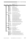
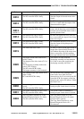
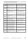
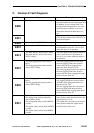
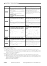
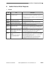
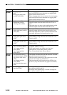
Cause
• The CCD PCB is faulty.
• The image processor PCB is faulty.
• The wiring is faulty (short circuit, open
circuit).
• The CCD PCB is faulty.
• The image processor PCB is faulty.
• The wiring is faulty (short circuit, open
circuit).
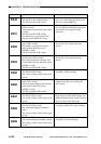
• The image processor PCB is faulty.
• The MFC PCB is faulty.
• The wiring is faulty (short circuit, open
circuit).
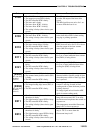
• The image server (hard disk) is faulty.
• The image processor PCB is faulty.
• The MFC PCB is faulty.
• The wiring is faulty (short circuit, open
circuit).
• The image server (hard disk) is faulty.
• A printer board (accessory) is faulty.
• The MFC PCB is faulty.
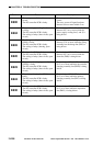
• The system motherboard is faulty.
• The DC controller PCB is faulty.
• The ADF controller PCB is faulty.
• The finisher controller PCB is faulty.
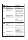
• The DC controller PCB is faulty.
• The ADF controller PCB is faulty.
• The finisher controller PCB is faulty.
• The ADF controller PCB is faulty.
• The connector has poor contact.
• The 24-V power supply is faulty.
• The DC controller PCB is faulty.
• The finisher controller PCB is faulty.
• The connector has poor contact.
• The 24-V power supply is faulty.
• The DC controller PCB is faulty.
• The Copy Data Controller-A1 or the
Remoto Diagnostic Device II is faulty.
• The wiring is faulty (short circuit, open
circuit).
Description
• The shading end signal from the CCD
PCB does not reach the image processor
PCB during shading operation.
• The image read end signal from the CCD
PCB does not reach the image processor
PCB within 60 sec during image reading
operation.
• The MFC PCB has detected an error in
control data during image transfer
between the MFC PCB and the image
server.
• The image processor PCB has detected an
error in image transfer between the MFC
PCB and the image processor PCB.
• An error has been detected in the image
data when the image processor PCB
writes to or reads from the image server.
• An error has occurred in the
communication between a printer board
(accessory) and the MFC PCB.
• The IPC (IC12) on the DC controller
PCB cannot be initialized at power-on.
• The IPC (IC12) on the DC controller
PCB is out of order at power-on.
• The communication control IC on the
ADF controller PCB is out of order.
• The communication control IC on the
finisher controller PCB is out of order.
• The PC of the Copy Data Controller-A1
or the Remoto Diagnostic Device II is
out of order.
Code
E302
E320
E601
E602
E677
E710
E711
E713
E712
E717
(NOTE 1)