CHAPTER 13 TROUBLESHOOTING
13-86
COPYRIGHT
©
1999 CANON INC. CANON imageRUNNER 600 REV.1 JAN. 2000 PRINTED IN U.S.A.
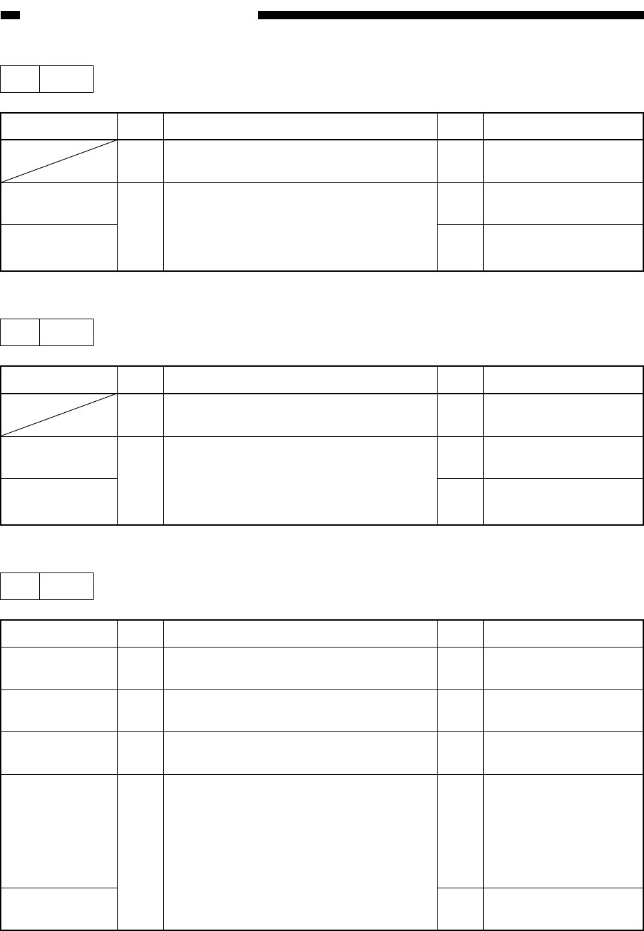
10 E014
Step
1
2
Action
Connect the connector.
Replace the DC
controller PCB.
Replace the pickup
motor.
Checks
Is the connector of the pickup motor
connected?
Does the voltage between J513-A3 (+)
and J513-A1 (-) on the DC controller
PCB change from 0 to about 5 V when
the Copy start key is pressed?
Yes/No
NO
NO
YES
Cause
DC controller
PCB
Pickup motor
(M2)
11 E015
Step
1
2
Action
Connect the connector.
Replace the DC
controller PCB.
Replace the pickup
motor.
Checks
Is the connector of the pickup motor
connected?
Does the voltage between J513-A3 (+)
and J513-A1 (-) on the DC controller
PCB change from 0 to about 5 V when
the Copy Start key is pressed?
Yes/No
NO
NO
YES
Cause
DC controller
PCB
Pickup motor
(M2)
12 E019
Step
1
2
3
4
Action
Dispose of the waste
toner.
Correct the movement.
Connect the connector
securely.
Check the connection
of the cable up to the
DC controller PCB; if
normal, replace the
waste toner sensor
(PS19).
Replace the DC
controller PCB.
Checks
Is the waste toner case full?
Is the movement of the waste toner mount
smooth?
Is the connector (J514) on the DC
controller PCB connected securely?
Replace the waste toner sensor (PS19). Is
the problem corrected?
Yes/No
NO
NO
NO
YES
NO
Cause
Waste toner
Waste toner case
mount
Connect the
connector
Waste toner
case sensor
DC controller
PCB


