10-36
COPYRIGHT
©
1999 CANON INC. CANON imageRUNNER 600 REV.1 JAN. 2000 PRINTED IN U.S.A.
CHAPTER 10 SIDE PAPER DECK
6. Removing the Lifter Cable (rear of
the deck)
1) Open the deck, and remove all paper.
2) Remove the screw, and detach the paper
trailing edge guide plate from inside the
compartment.
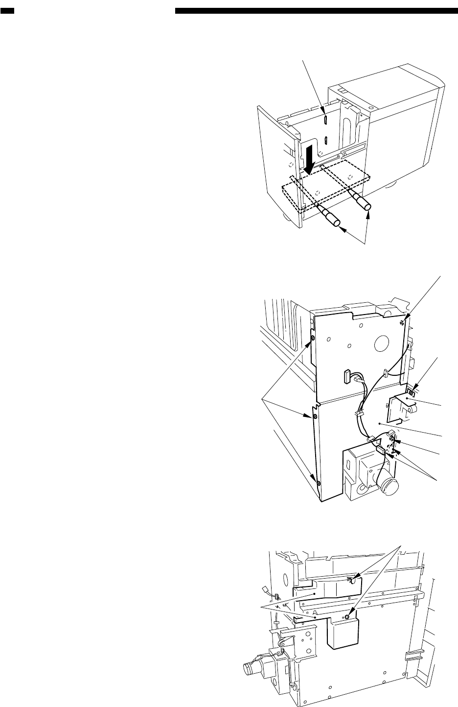
3) Push down the lever [1] of the paper sup-
ply position sensor inside the compart-
ment to move down the lifter until the left
and right holes in the compartment side
plate and the left and right holes of the
lifter match; then, insert two long screw-
drivers [2] through the holes.
At this time, match the top surface of the
lifter with the marking on the compart-
ment left side plate to facilitate matching
the holes.
4) Remove the compartment. (See p. 10-28.)
5) Remove the screw [3], and detach the sen-
sor plate [4].
6) Remove one screw each [5], and detach
the sensor cover upper/lower [6].
7) Disconnect the two connectors [7], and re-
move the five screws [8]; then, detach the
metal plate [9].
Figure 10-C310
Figure 10-C311
Figure 10-C312
[1]
[2]
[8]
[8]
[3]
[4]
[9]
[8]
[7]
[5]
[6]


