COPYRIGHT
©
1999 CANON INC. CANON imageRUNNER 600 REV.1 JAN. 2000 PRINTED IN U.S.A.
9-37
CHAPTER 9 EXTERNALS/AUXILIARY MECHANISMS
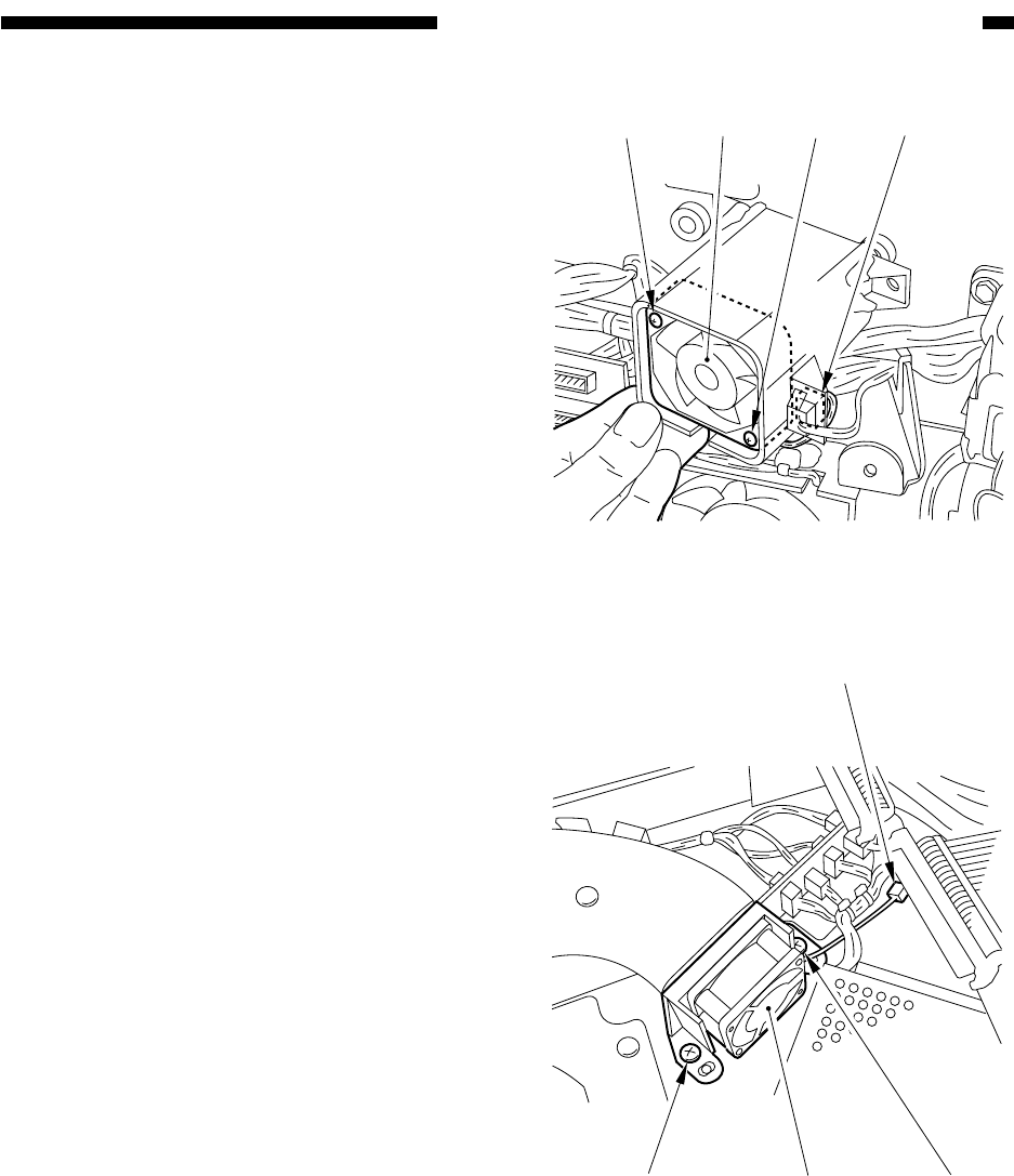
Figure 9-C707
[4] [4][5] [3]
[1]
[2]
[1]
[3]
Figure 9-C708
5) Disconnect the connector [3], and remove
the two screws [4]; then, detach the stream
reading fan [5].
5. Removing the Laser Cooling Fan
1) Remove the copyboard glass.
2) Remove the original sensor unit 1.
3) Remove the image processor cover, and
detach the image processor PCB.
4) Remove the two screws [1], and discon-
nect the connector [2]; then, detach the la-
ser cooling fan [3] together with its
mount.


