9-50
COPYRIGHT
©
1999 CANON INC. CANON imageRUNNER 600 REV.1 JAN. 2000 PRINTED IN U.S.A.
CHAPTER 9 EXTERNALS/AUXILIARY MECHANISMS
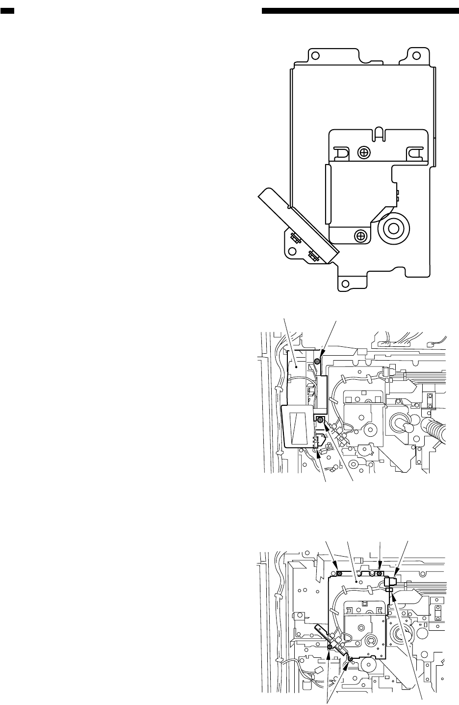
Figure 9-D703
[3]
[1]
[1][2]
[5] [5] [4][6]
[5]
[4]
Figure 9-D704
3. Removing the Developing Drive
Assembly
Construction
1) Remove the rear cover.
2) Remove the high-voltage transformer
(DC). (See Figure 9-I701.)
3) Remove the flywheel. (See Figure 9-
D712.)
4) Remove the drum gear. (See Figure 9-
D713.)
5) Remove the waste toner pipe. (See Figure
9-D715.)
6) Remove the drum drive assembly. (Figure
9-D717.)
7) Remove the waste toner drive assembly.
(See Figure 9-D707.)
8) Remove the two screws [1], and discon-
nect the connector [2]; then, detach the
drum fan [3].
9) Disconnect the two connectors [4], and re-
move the four screws [5]; then, detach the
developing drive assembly [6].


