CHAPTER 6 IMAGE FORMATION SYSTEM
6-46
COPYRIGHT
©
2000 CANON INC. CANON imageRUNNER 600 REV.1 JAN. 2000 PRINTED IN U.S.A.
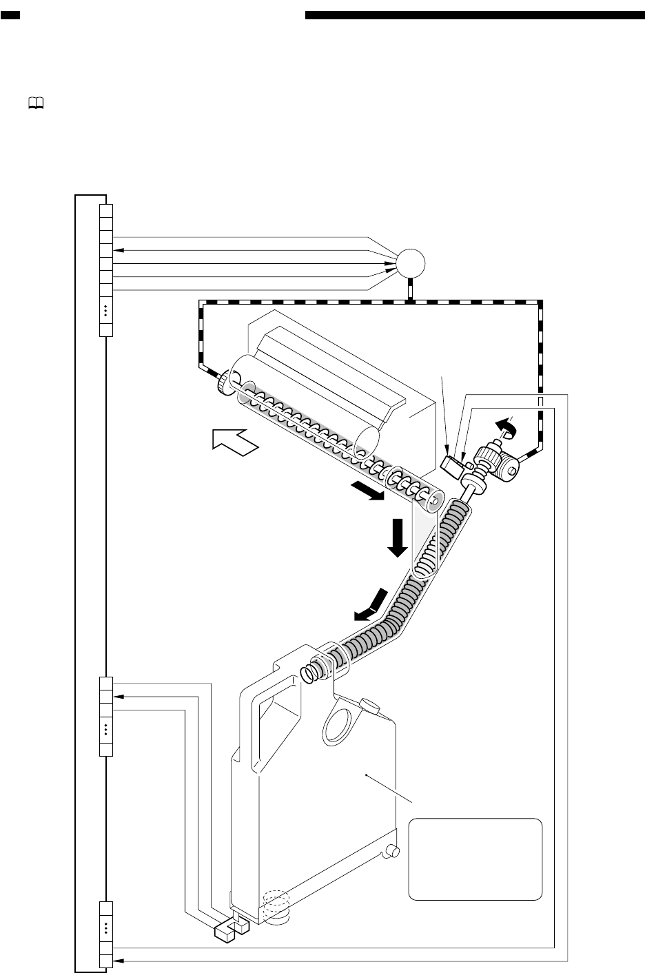
B. Detecting the Waste Toner (case full condition)
Part 2>Chapter 5>9>9.2
Figure 6-502 shows the construction of the control system used to monitor the waste toner
case.
Figure 6-502 Construction of the Control System
DC controller PCB
Waste toner case
(front)
J514B
J514A
J512B
MM-FG
0V
5V
WT-RCK
WT-FULL
5V
0V
MM-ON
5V
0V
1
4
3
2
5
6
7
14
1
3
2
14
1
13
14
M1
Main motor
Waste toner case full sensor (PS19)
Waste toner
lock sensor
(MSW2)
As toner collects, the
case becomes heavy,
causing the waste
toner case sensor to
detect the flag.


