COPYRIGHT
©
1999 CANON INC. CANON imageRUNNER 600 REV.1 JAN. 2000 PRINTED IN U.S.A.
11-43
CHAPTER 11 INSTALLATION
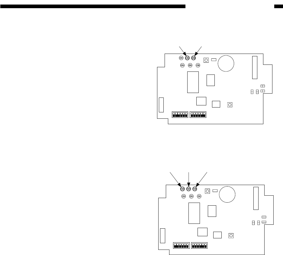
Figure 11-C603
Figure 11-C604
16
SW4
SW1
ON
SW5
ON
LED6LED5LED4
LED3LED2LED1
SW2
SW3
JB2
JB1
JA1
JA2
EPROM
SRAM
CPU
IPC
JC9
JC6
JC5
JC8
J5
16
LED2 LED3
Photocoupler
3) Turn on the copier's main switch, and
check to make sure that LED2 of the con-
troller flashes.
Make a copy, and check to make sure that
LED3 flashes during copying operation.
4) If the Communications Board-A1 or the
Interface Board-B1 is to be connected (re-
quiring the Power Supply-A1), go to 5).
Turn on the copier's main switch, and
check to make sure that LED1 of the con-
troller turns on and LED2 turns off.
Make a copy, and check to make sure that
LED3 flashes during copying operation.
16
SW4
SW1
ON
SW5
ON
LED6LED5LED4
LED3LED2LED1
SW2
SW3
JB2
JB1
JA1
JA2
EPROM
SRAM
CPU
IPC
JC9
JC6
JC5
JC8
J5
16
LED1
LED3
LED2
Photocoupler


