COPYRIGHT
©
1999 CANON INC. CANON imageRUNNER 600 REV.1 JAN. 2000 PRINTED IN U.S.A.
3-5
CHAPTER 3 ORIGINAL EXPOSURE SYSTEM
II . SCANNER DRIVE SYSTEM
A. Outline
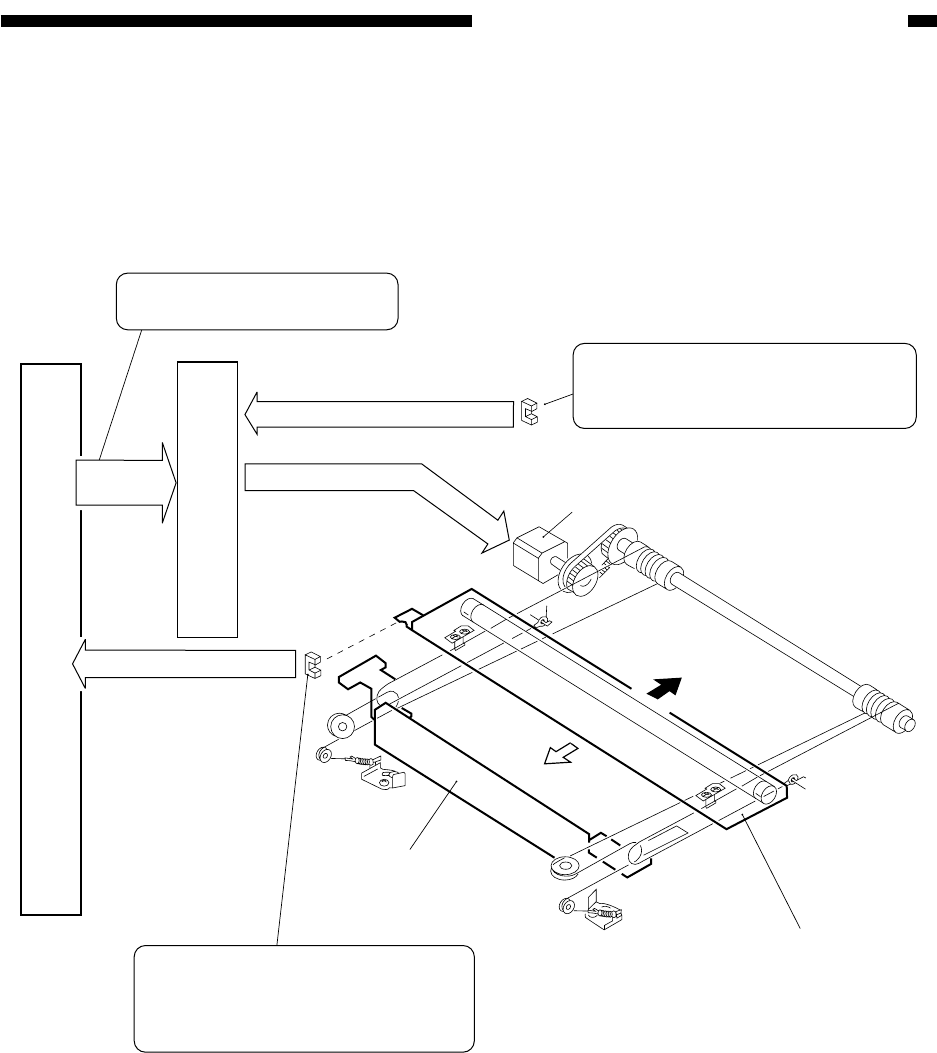
Figure 3-201 shows the components of the scanner drive system.
Figure 3-201 Components of the Scanner Drive System
DC controller PCB
Scanner motor driver PCB
Scanner motor (M5)
Scanner HP sensor (PS1)
Copyboard glass sensor (PS57)
(forward)
(reverse)
No. 2 mirror mount
No. 1 mirror mount
Drive signal
Detection signal
Detection signal
[1] Direction of motor rotation
[2] Speed of motor rotation
Used to detect the presence/absent
of the copyboard glass. If absent,
the drive signal to the motor is off.
Used to detect the home position of
the No. 1 mirror mount. The No. 1
mirror mount is stopped in reference
to this signal.
Control
signal


