COPYRIGHT
©
2000 CANON INC. CANON imageRUNNER 600 REV.1 JAN. 2000 PRINTED IN U.S.A.
8-9
CHAPTER 8 FIXING SYSTEM
D. Controlling the Fixing Inlet Guide Drive Mechanism
Part 2>Chapter 7>5.5
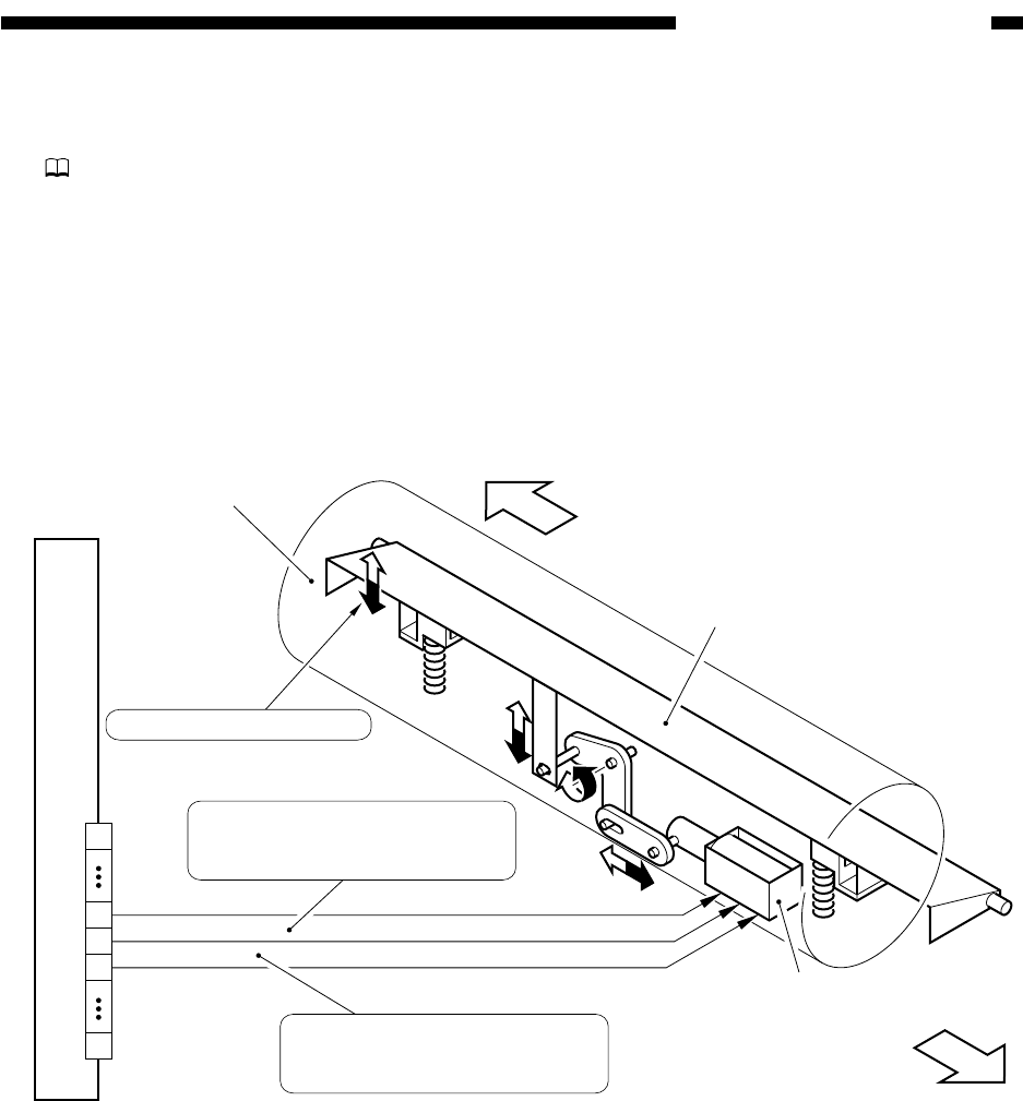
Figure 8-204 shows the construction of the control system used to control the fixing inlet guide
drive mechanism.
Figure 8-204 Construction of the Control System
Fixing inlet guide
solenoid (SL1)
DC controller PCB
J508B
24V
FIXG-DWN
FIXG-UP
(front)
Inlet guide
(rear)
Upper fixing roller
1
20
11
12
13
Top/bottom width: 1.8 mm
When '0', the fixing inlet guide
moves down. (paper length less
than 300 mm)
When '0', the fixing inlet guide
moves up. (paper length 300
mm or more)


