COPYRIGHT
©
2000 CANON INC. CANON imageRUNNER 600 REV.1 JAN. 2000 PRINTED IN U.S.A.
6-63
CHAPTER 6 IMAGE FORMATION SYSTEM
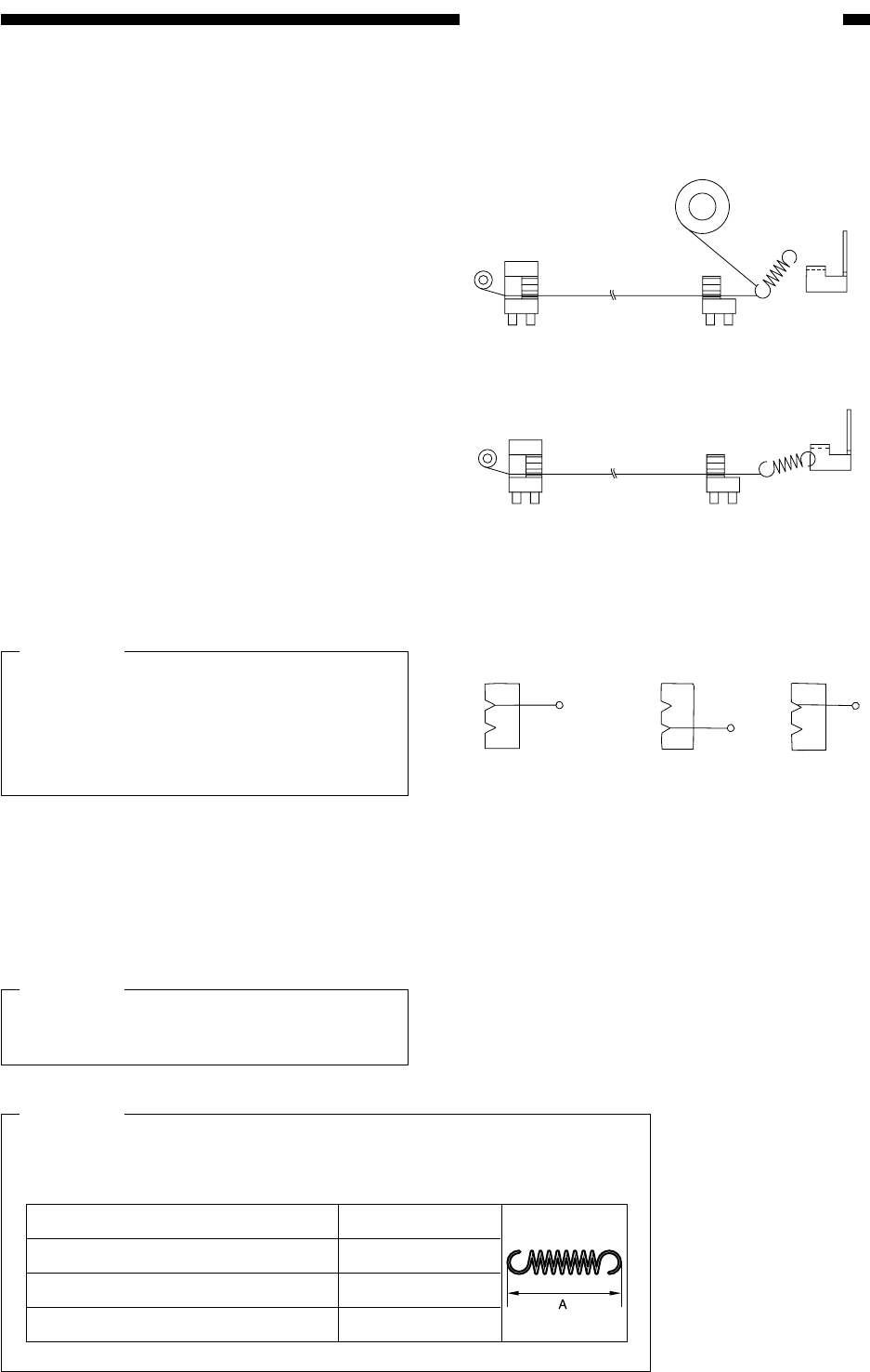
Figure 6-C709
Figure 6-C711
Figure 6-C710
Grid side
Correct
Wrong
4) Cut off the twisted end of the wire (ex-
cess) with a nipper.
5) Hook the loop on the stud.
6) At the rear side, hook the charging wire on
the charging wire positioner; then, hook
and twist the charging wire tensioning
spring on the charging wire.
7) Cut the excess charging wire with a nip-
per.
8) Pick the end of the charging wire
tensioning spring with tweezers, and hook
it on the charging wire electrode. (In the
case of the pre-transfer charging assem-
bly, hook the spring on the pin at the
front.)
Caution:
Check the following:
• The charging wire must not be bent or
twisted.
• The charging wire must be in the V-
groove of the charging wire positioned.
9) Mount the cushion at the front of the
charging wire (except the primary charg-
ing assembly).
10) Mount the shielding plate (left, right).
Caution:
For other charging assemblies, mount
the lids (2 pcs.).
Primary charging assembly
Pre-transfer charging assembly
Transfer charging assembly
Separation charging assembly
A=12.0±1mm
A=12.0±1mm
A=12.0±0.5mm
A=12.0±0.5mm
Caution:
After stinging the charge wire for each charging assembly, check to
make sure that the length of each tension spring is as follows:


