11-38
COPYRIGHT
©
1999 CANON INC. CANON imageRUNNER 600 REV.1 JAN. 2000 PRINTED IN U.S.A.
CHAPTER 11 INSTALLATION
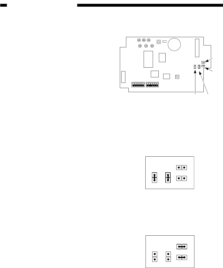
Figure 11-A604
Figure 11-A603
Figure 11-A605
3) Set the jumper connectors (JA1, JA2, JB1,
JB2) on the controller to suit the needs of
the user.
A: If the Communication Control Board-A1
or the Interface Board-B1 is to be con-
nected (requiring the Power Supply-A1).
B: If the Communication Control Board-A1
or the Interface Board-B1 is not to be con-
nected (not requiring the Power Supply-
A1).
16
SW4
SW1
ON
SW5
ON
LED6LED5LED4
LED3LED2LED1
SW2
SW3
JB2
JA1
JA2
EPROM
SRAM
CPU
IPC
JC9
JC6
JC5
JC8
J5
JB1
JB2
JA2
JA1
16
Photocoupler
JB1JB2
JA2
JA1


