COPYRIGHT
©
1999 CANON INC. CANON imageRUNNER 600 REV.1 JAN. 2000 PRINTED IN U.S.A.
6-37
CHAPTER 6 IMAGE FORMATION SYSTEM
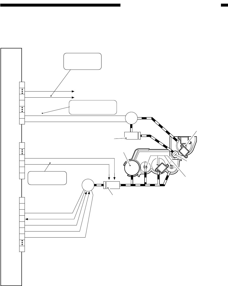
Figure 6-402 Construction of the Control System
B. Controlling the Developing Assembly
Figure 6-402 shows the construction of the control system.
MGR-CL-ON
24VU
DEV-CL-ON
24VU
J512A
MM-FG
0V
MM-ON
5V
0V
J514B
0V
HM-ON
J504B
M1
M18
CL4
To CL1
Magnet roller
Toner feeding screw
Toner stirring screw
Main motor
Developing cylinder clutch
Developing cylinder
CL1
DC controller PCB
1
13
14
18
19
1
2
3
4
5
6
7
14
1
11
12
13
14
The motor turns on
in response to 24 V.
Toner feed motor
(inside the hopper)
Magnet roller
drive clutch
When '0', the
clutch turns on.
When '0', the
clutch turns on.


