CHAPTER 7 PICK-UP/FEEDING SYSTEM
7-62
COPYRIGHT
©
1999 CANON INC. CANON imageRUNNER 600 REV.1 JAN. 2000 PRINTED IN U.S.A.
[1]
[2]
[1]
[2]
A
Viewed from A
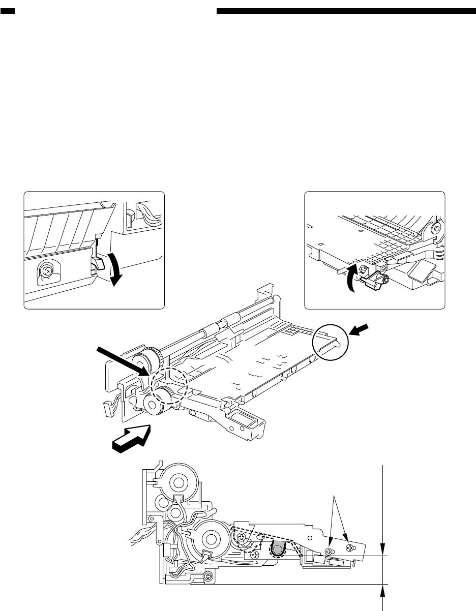
36±0.5mm
[3]
Figure 7-B816
11. Position of the Pickup Roller
Releasing Solenoid of the
Cassette (3/4)
As shown in Figure 7-B816, adjust the po-
sition of the solenoid by using the two screws
[3] so that the distance from the bottom of the
pickup assembly and section A of the roller
arm is 36 ±0.5 mm when [1] and [2] are oper-
ated.


