CHAPTER 2 BASIC OPERATIONS
2-6
COPYRIGHT
©
1999 CANON INC. CANON imageRUNNER 600 REV.1 JAN. 2000 PRINTED IN U.S.A.
D. Controlling the Main Motor (M1)
1. Outline
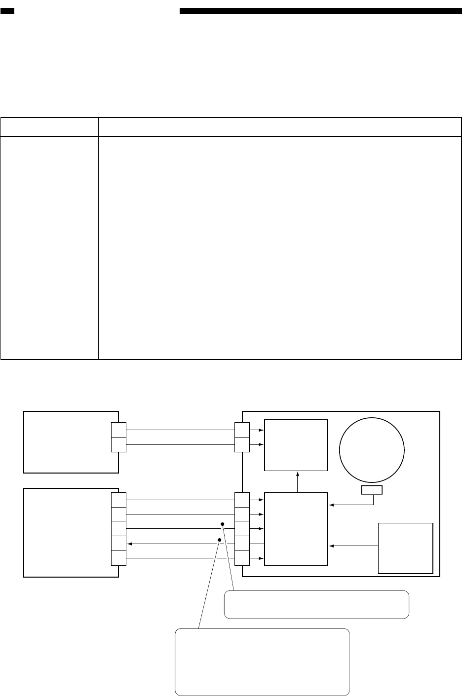
Table 2-108 shows the functions of the main motor control circuit, and Figure 2-104 is a block
diagram of the circuit.
Table 2-108
Figure 2-104 Control Circuit Block Diagram
Drive circuit
Control
panel
Reference
signal
generation
circuit
Clock pulse
generation
circuit
J612
J611
J514
J1720
DC controller
PCB
Relay PCB
1
2
1
2
3
4
5
1
2
B7
B6
B5
B4
B3
38V
5V
0V
0V
GND
MAIN_MOTOR_ON
MAIN_MOTOR_FG
Main motor
(M1)
When the main motor drive signal
goes '1', the main motor starts to rotate.
When the main motor starts to rotate,
the pulse signal goes '1'.
When the pulse signal goes '0', error
code E010 is indicated.
Item
Power supply
Drive signal
Operating/drive
assembly
Control
Error detection
Description
38 V from the relay PCB.
Signals (MAIN_MOTOR_ON) from the DC controller PCB.
Waste toner feeding screw
Cleaner assembly
Feeding belt
Internal delivery roller
External delivery roller
Reversing roller
Separation claw (reciprocating operation)
Developing assembly unit (through CL10)
ON/OFF control
Constant speed control
Error code E010


