CHAPTER 13 TROUBLESHOOTING
13-32
COPYRIGHT
©
1999 CANON INC. CANON imageRUNNER 600 REV.1 JAN. 2000 PRINTED IN U.S.A.
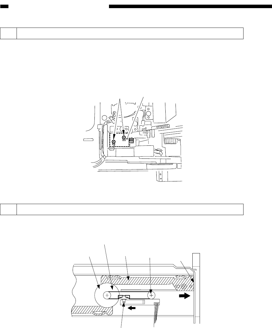
9.9 Position of the Side Paper Deck Pickup Roller Releasing Solenoid
[2]
[1]
10 Routing the Manual Feed Tray Assembly Side Guide Timing Belt
Figure 13-D219
Pulley
Timing belt
Rack plate
Pulley
Section A
B
Slide volume
Before removing the deck pickup roller releasing solenoid [1] from the support plate, keep note
of the positions of the two fixing screws [2] of the solenoid with reference to the scale graduations
on the support plate; or, mark the position of the solenoid (of itself) on the support plate with a
scriber.
If you are mounting the solenoid on its own, be sure to secure it in place in its initial position.
Figure 13-D218
Butt the rack plate of the manual feed tray against section A (open condition).
Move the slide volume into the direction of B, and attach the timing belt to the pulley.


