CHAPTER 8 FIXING SYSTEM
8-2
COPYRIGHT
©
1999 CANON INC. CANON imageRUNNER 600 REV.1 JAN. 2000 PRINTED IN U.S.A.
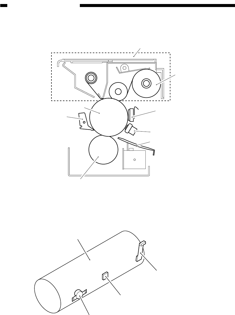
Figures 8-101 and -102 show the major components of the fixing system.
Figure 8-101 Cross Section
Figure 8-102 External View
Cleaning belt unit
Upper fixing roller
Separation claw
Lower fixing roller
Cleaning belt
Main thermistor (TH1)
Sub thermistor (TH2)
Thermal switch (TP1)
Inlet guide
Upper fixing roller
Sub thermistor (TH2)
Main thermistor (TH1)
Thermal switch (TP1)


