4-24
COPYRIGHT
©
2000 CANON INC. CANON imageRUNNER 600 REV.1 JAN. 2000 PRINTED IN U.S.A.
CHAPTER 4 IMAGE PROCESSING SYSTEM
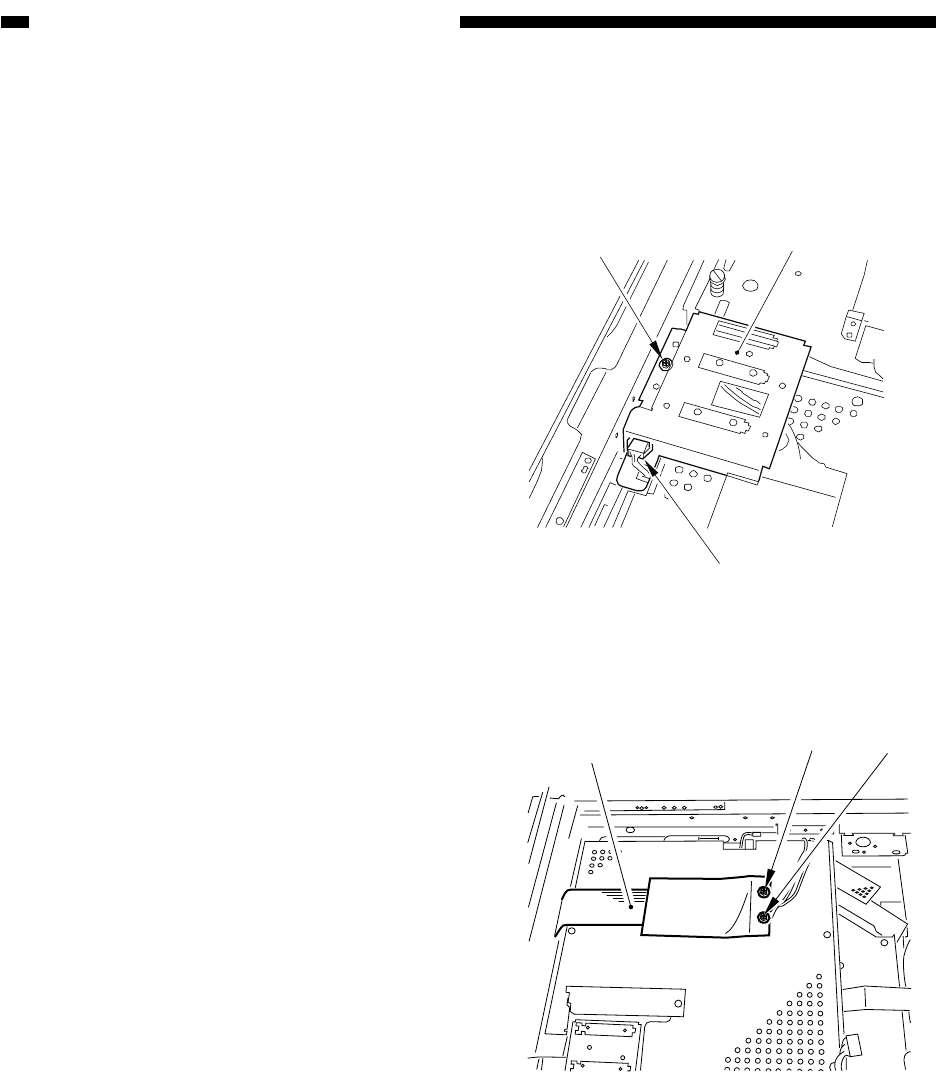
Figure 4-B401
Figure 4-B402
[1]
[2]
[3]
[5]
[4]
[4]
B. Image Processor PCB
1. Removing the Image Processor
PCB
1) Remove the copyboard glass.
2) Move the No. 1 mirror mount to the left
edge.
3) Remove the one screw [1], and disconnect
the connector [2]; then, detach the original
sensor unit (rear) [3].
4) Remove the two screws [4], and detach
the flat cable [5].


