


COPYRIGHT
©
1999 CANON INC. CANON imageRUNNER 600 REV.1 JAN. 2000 PRINTED IN U.S.A.
v
CHAPTER 1 GENERAL DESCRIPTION
I. FEATURES ................................ 1-1
II. SPECIFICATIONS...................... 1-2
A. Copier .................................... 1-2
1. Type ................................. 1-2
2. System ............................. 1-2
3. Performance ..................... 1-3
4. Others............................... 1-7
B. Side Paper Deck-C1 ............ 1-10
III. NAMES OF PARTS .................. 1-11
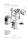
A. External View ...................... 1-11
B. Cross Section ...................... 1-14
IV. OPERATING THE COPIER ..... 1-16
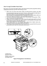
A. Turning on the Power Switch
............................................ 1-16
B. Control Panel .......................1-17
C. Extension Mode................... 1-18
D. User Mode........................... 1-19
V. ROUTINE MAINTENANCE BY THE
USER ....................................... 1-21
VI. SAFETY ................................... 1-22
A. Safety of Laser Light ........... 1-22
B. CDRH Regulations .............. 1-23
C. Handling the Laser Assembly
............................................ 1-24
D. Safety of Toner.................... 1-28
VII. IMAGE FORMATION ............... 1-29
A. Outline ................................. 1-29
CONTENTS
CHAPTER 2 BASIC OPERATIONS
I. BASIC OPERATIONS ................ 2-1
A. Functional Construction......... 2-1
B. Electrical Circuitry .................. 2-2
1. Outline ..............................2-2
2. MFC PCB ......................... 2-2
3. Image Processor PCB ...... 2-2
4. DC Controller PCB ........... 2-3
5. Control panel CPU PCB ... 2-3
6. Original Orientation Detection
PCB .................................. 2-3
7. Image Server .................... 2-3
C. Basic Sequence of Operations
.............................................. 2-5
1. Basic Sequence of
Operations (power-on) ..... 2-5
D. Controlling the Main Motor (M1)
.............................................. 2-6
1. Outline ..............................2-6
E. Inputs to and Outputs from the
Major PCBs ........................... 2-7
1. Wiring Diagram of Major
PCBs ................................ 2-7
2. Inputs to the DC Controller
PCB .................................. 2-8
3. Outputs from the DC
Controller PCB ............... 2-14
CHAPTER 3 ORIGINAL EXPOSURE SYSTEM
I. OPERATIONS ............................ 3-1
A. Outline ................................... 3-1
B. Basic Sequence of Operations
.............................................. 3-3
C. Changing the Reproduction Ratio
.............................................. 3-4
II. SCANNER DRIVE SYSTEM ...... 3-5
A. Outline ................................... 3-5
B. Controlling the Scanner Motor
.............................................. 3-6
III. CONTROLLING THE SCANNING
LAMP.......................................... 3-8