COPYRIGHT
©
1999 CANON INC. CANON imageRUNNER 600 REV.1 JAN. 2000 PRINTED IN U.S.A.
6-41
CHAPTER 6 IMAGE FORMATION SYSTEM
E. Detecting the Toner Level and Controlling the Toner Supply
Mechanism
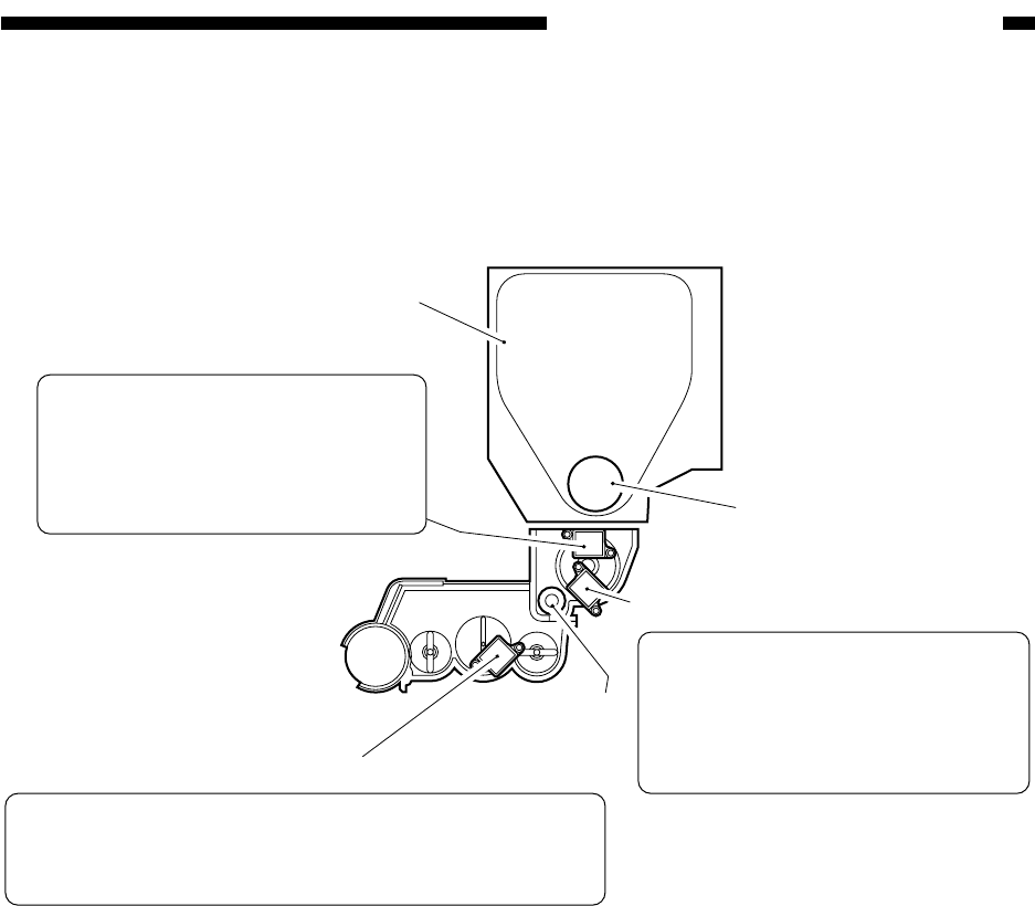
Figure 6-406 shows the construction of the toner supply control system.
Figure 6-405
Magnet roller
Toner sensor (TS1; inside the hopper)
Toner cartridge
Toner feeding screw
Toner lower limit sensor
(TS2; inside the hopper)
Toner sensor
(TS3; inside the developing assembly)
Purpose: To keep the toner inside the
hopper to a specific level.
Operation: If the absence of toner is
detected, the toner feeding screw inside
the toner cartridge is rotated to supply the
hopper with toner.
Purpose: To keep the toner inside the developing assembly to a
specific level.
Operation: If the absence of toner is detected, the magnet roller is
rotated to supply the developing assembly with toner.
Purpose: To detect the absence of toner
inside the hopper.
Operation: If the absence of toner is
detected, the ongoing operation is
stopped, and the Add Toner message will
be indicated.


