COPYRIGHT
©
1999 CANON INC. CANON imageRUNNER 600 REV.1 JAN. 2000 PRINTED IN U.S.A.
9-33
CHAPTER 9 EXTERNALS/AUXILIARY MECHANISMS
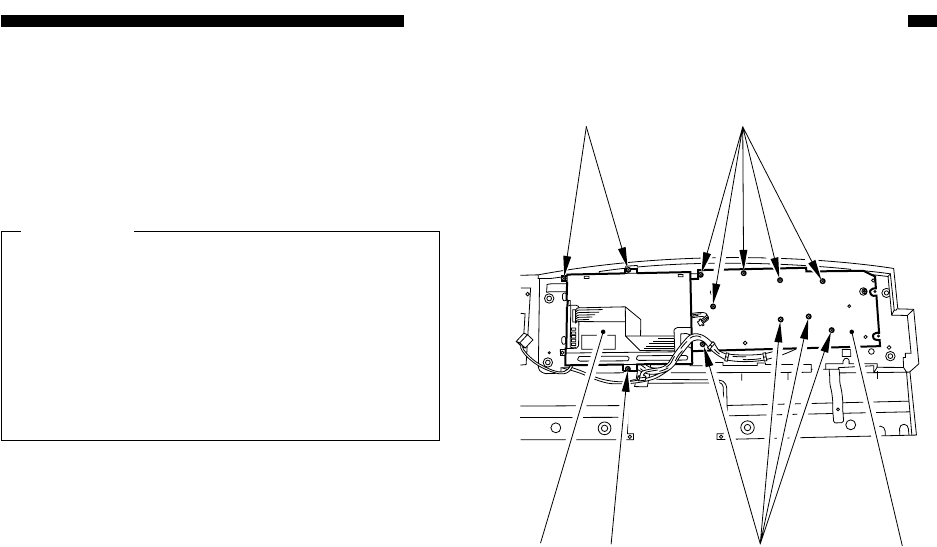
Figure 9-B709
[7]
[5]
[5] [6][7][8]
4) Remove the nine screws [5], and detach
the control panel PCB [6]; then, remove
the three screws [7], and detach the LCD
panel [8].
Caution:
When mounting the control panel PCB
or the LCD panel to the control panel,
keep in mind that some locations need to
be screwed together with the CPU PCB
mounting plate (2 locations on the con-
trol panel PCB, 2 locations on the LCD
panel).


