COPYRIGHT
©
2000 CANON INC. CANON imageRUNNER 600 REV.1 JAN. 2000 PRINTED IN U.S.A
3-19
CHAPTER 3 ORIGINAL EXPOSURE SYSTEM
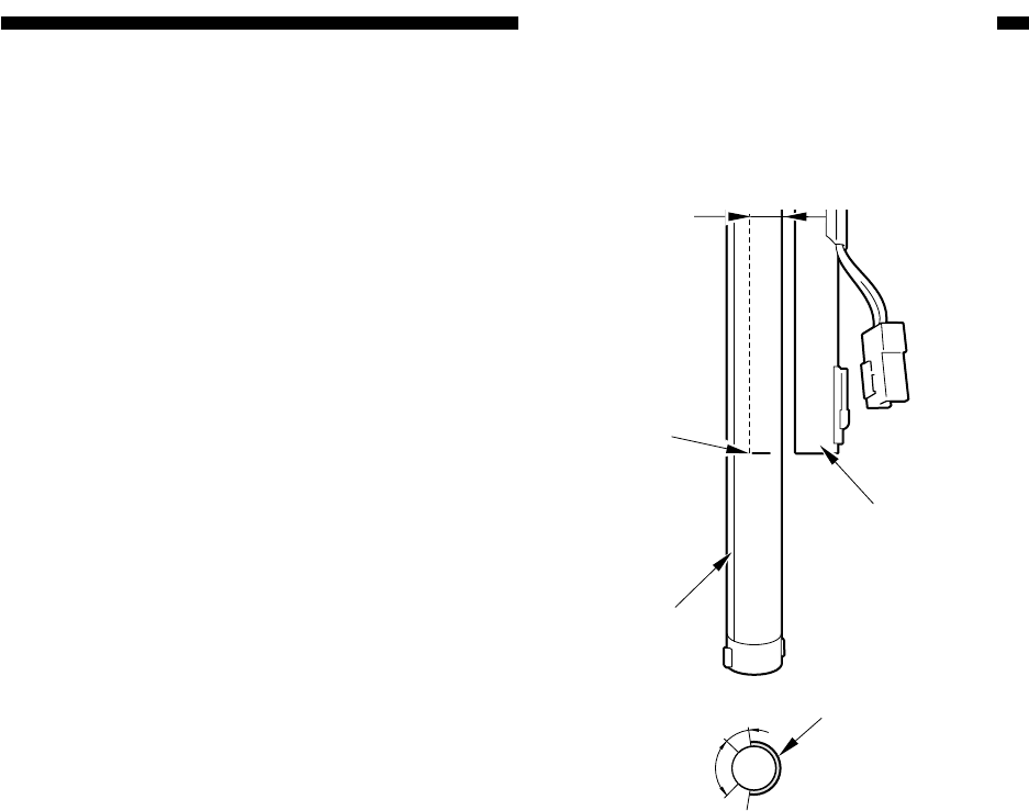
Figure 3-A509
Marking
4 mm (approx.)
Light-emitting
side
Heater
Heater
Light-emitting
side
Upper : 6 to 7 mm (approx.)
2. Points to Note When Replacing
the Scanning Lamp
• Do not start working if the surface of the
scanning lamp is hot.
• Do not leave fingerprints on the surface of
the scanning lamp.
• Dry wipe the surface of the scanning lamp if
soiled.
• When mounting the scanning lamp heater to
the scanning lamp, be sure to match the
markings. (The connector of the scanning
lamp heater must be toward the front of the
copier.)
• When mounting the scanning lamp to the
copier, take care not to touch its light-emit-
ting side.
• When mounting the scanning lamp to the
copier, be sure that the print/marking is to-
ward the upper front of the copier.
3. After Replacing the Scanning
Lamp
1) Execute
COPIER>FUNCTION>CCD>CCD-ADJ
in service mode.
2) When all items of
COPIER>ADJUST>CCD and data of
COPIER>ADJUST>LAMP>L-DATA
have been updated, record them on the
service label.


