CHAPTER 7 PICK-UP/FEEDING SYSTEM
7-64
COPYRIGHT
©
2000 CANON INC. CANON imageRUNNER 600 REV.1 JAN. 2000 PRINTED IN U.S.A.
[3]
[3]
[4]
[1]
[2]
[2]
[3]
[3]
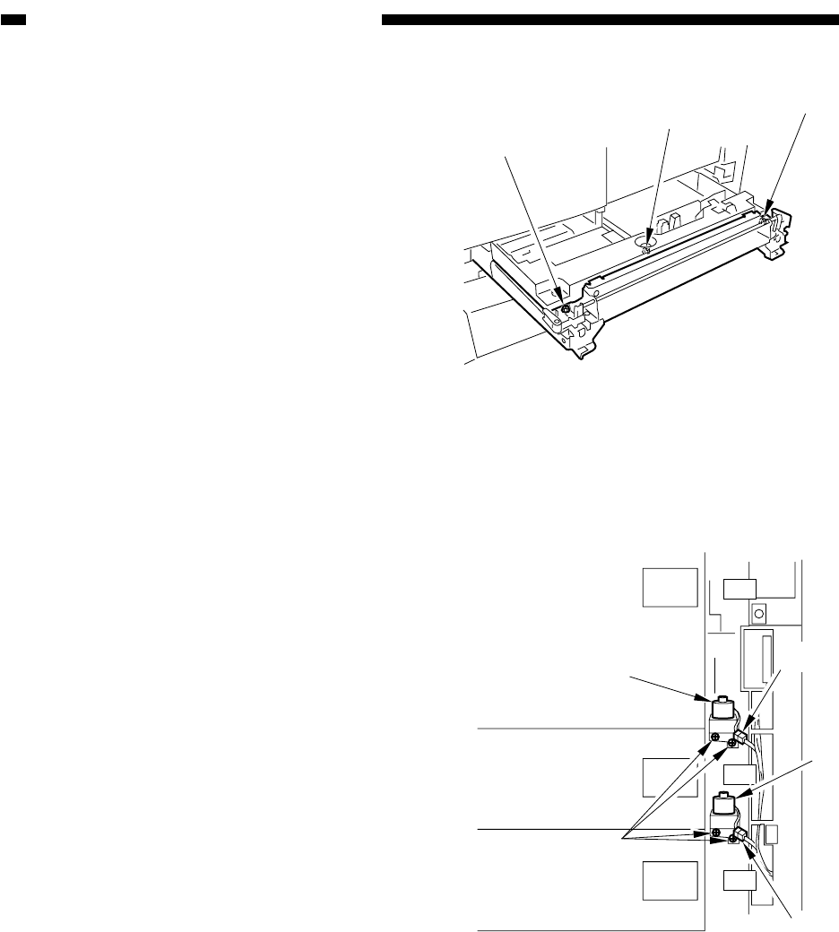
Figure 7-B820
Figure 7-B821
2) Loosen the two fixing screws [3] on the
cassette (left/right), and make adjustments
using the adjusting screw [4].
After adjustment, be sure to execute
COPIER>FUNCTION>CST>C3-
STMTR/AR or C4-STMTR/A4R in
service mode.
14. Removing the Lifter Motor (M16/
M17) of the Cassette (3/4)
1) Slide out the front deck (right); then, slide
out the cassette 3/4.
2) Remove the front lower right cover of the
cassette assembly as instructed under C.2.
"Removing the Vertical Path Roller 2."
3) Remove the two fixing screws [1] of the
lifter motor (M16/M17), and disconnect
the connector [2]; then, detach the lifter
motor [3].


