CHAPTER 3 ORIGINAL EXPOSURE SYSTEM
3-6
COPYRIGHT
©
1999 CANON INC. CANON imageRUNNER 600 REV.1 JAN. 2000 PRINTED IN U.S.A.
B. Controlling the Scanner Motor
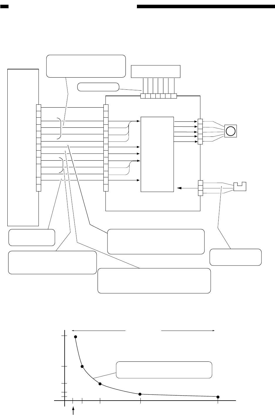
Figure 3-202 shows the construction of the scanner motor control mechanism.
Figure 3-202 Construction of the Control System
Figure 3-203 Relationship between Motor Speed and Reproduction Ratio
Scanner motor
Copyboard
glass sensor
DC controller PCB
Scanner motor driver PCB
Relay PCB
J506A
J802
J803
J801
M5
PS57
1
2
3
4
5
1
234567
J804
1
2
3
0 V
0 V
5 V
GLS_DT
OPT-D0
OPT-CD0
OPT-CD1
OPT-CD2
OPT-D1
OPT-D2
OPT-D3
OPT-CLK
OPT-DWN
OPT-CCW
Not used
Not used
38 VU
GND
GND
GND
12 V
5 V
-12 V
1
2
3
4
5
6
7
8
9
10
11
12
13
1
2
3
4
5
6
7
8
9
10
11
12
13
Excitation
control
The number of steps (clock
signals) is determined based on
combinations of D0 through D3.
For motor drive
The current to the motor is
determined based on combinations
of CD0 through CD2.
In the absent of the
copyboard glass,'1'.
Motor drive sync clock pulses; when '1',
the motor is at rest. The motor starts to
rotate in response to clock pulses.
Used to switch the direction of motor rotation:
when '1', the scanner moves forward; when
'0', the scanner moves in reverse.
When '1' power to
the motor is cut.
400%200%100%50%
25%/reverse
4000
2000
1000
500
8000
Motor speed (pps)
Current level
4.4A 0.9A
The scanner motor speed is varied
in increments of 1% (ratio).


