6-56
COPYRIGHT
©
1999 CANON INC. CANON imageRUNNER 600 REV.1 JAN. 2000 PRINTED IN U.S.A.
CHAPTER 6 IMAGE FORMATION SYSTEM
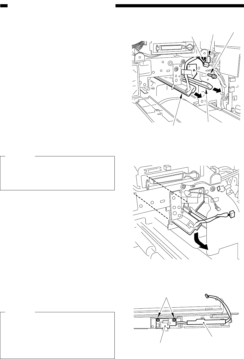
Figure 6-B704
Figure 6-B705
Figure 6-B706
[1]
[1]
[2]
[3]
[4]
[5]
[6]
[7]
2. Removing the Potential Sensor
Unit
1) Open the front cover.
2) Remove the process unit.
3) Push in the fixing/feeding assembly.
4) Disconnect the two connectors [1], and
pull out the dust-proofing glass [2]; then,
remove the screw [3], and detach the po-
tential sensor unit [4].
Caution:
It is difficult to pull out the potential sen-
sor in a horizontal direction. As shown,
shift it down once, and then slide it out to
facilitate the work.
5) Remove the two screws [5], and detach
the potential sensor cover [6]; then, detach
the potential sensor [7].
Caution:
Replace the potential sensor simulta-
neously with the potential sensor PCB.
When mounting it, be sure to fit the boss
at its rear in the hole on the rear side of
the copier; then, match it on the front
side, and screw it in place.


